Continue to Site

Welcome to EDAboard.com

Welcome to our site! EDAboard.com is an international Electronics Discussion Forum focused on EDA software, circuits, schematics, books, theory, papers, asic, pld, 8051, DSP, Network, RF, Analog Design, PCB, Service Manuals... and a whole lot more! To participate you need to register. Registration is free. Click here to register now.

power amplifier design parameters

Status
Not open for further replies.

marinara27

Member level 1
Joined
Mar 18, 2010
Messages
39
Helped
0
Reputation
0
Reaction score
0
Trophy points
1,286
Activity points
1,540
power amplifier

hi all..
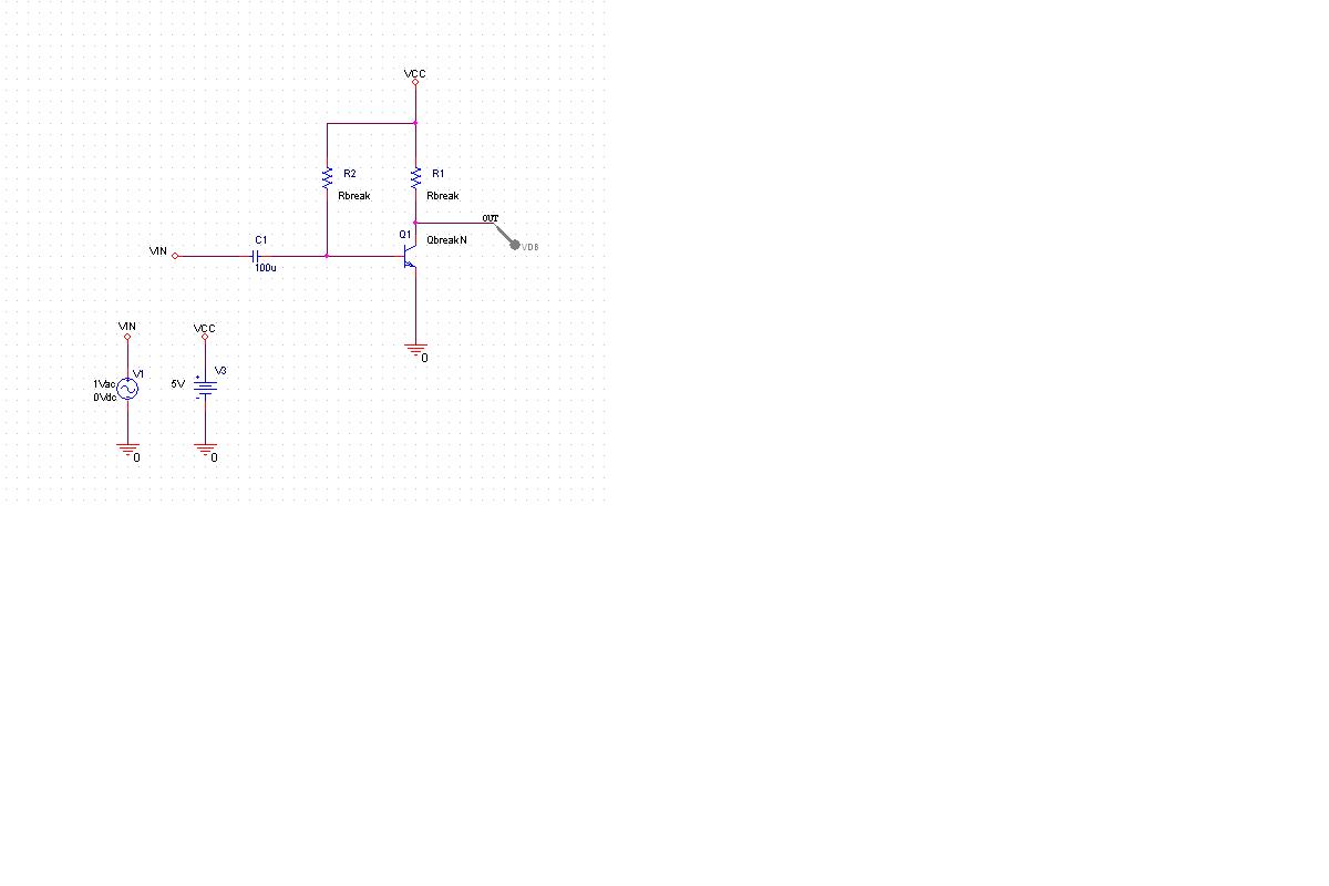
act, im doing the simulation for power amplifier circuit using pspice..
i analyze different classes of power amplifier such as class A,AB,B,C and D..

i really need help those expert in psice because i need to learn how to analyze these circuit using spice..
im using transient analysis,DC analysis and AC analysis..
can anyone help me how to do the monte carlo using AC analysis?
how to do the TF using DC analysis?

thanxs for your concern...
 

Re: power amplifier

well you can find the circuits in spice if you google it. If you have any specific query post the schematics and I can try to help. I posted one schematic for class C amplifier on edaboard, you can try to search it.

I have still not worked on the Monte carlo analysis but I have this document which can help you.Refer attached document for Monte carlo analysis

For noise Analysis take help from the manual of pspice to understand how to do it.
 

    marinara27

    Points: 2
    Helpful Answer Positive Rating
power amplifier

thanx you so much abbeyromy...
these paper really help me..
i did find in google..
but the value for each component not given...
so how do i decide each component's value..
do you know where to find the circuit..
 

power amplifier

well i would suggest you to go through university tutorials. (search in google with say "class A amplifier pspice") you will definitely find some links.

Finding the value of each component is all what designing is all about, I am sorry I wont be able to help you here as I am myself struggling with that part.

I will just give you an example of Class A amplifier design.
Design a Voltage Divider Bias configuration * you can find a circuit in any text book), Calculate levels of IB and IC at quiescent conditions. Make sure that the transistor is operationg in linear region IBsat> IB calculated.

Apply a small sinusoidal input at the base of transistor( common emitter amplifier). Depedning upon your values of R1,R2,Rc,RE you can find the DC level of output and AC gain Rc/re where re =26mv/IE

Now try to play with RC by reducing it and see how the gain reduces.

So the whole point is first understand the theory how the amplifier is working, go through basic transistor equations to see what parameters can effect gain, DC level, Frequency response etc. Once you understand these things you can yourself design the amplifier with your own values so as to meet the requirements

Even if you get a ready made circuit you would not understand as to why this value of R,L,C.

Work on a simulator and just play with it. Open text books and try to make the circuits as shown there. Then see what happens on changing these values ( Some circuits shown in book may not work as they may not be practical so dont worry just try)

I know some sites which can help u with pspice simulations-google them

ecircuitcenter.com
allaboutcircuits.com

Best of luck!
-Hemanshu
 

    marinara27

    Points: 2
    Helpful Answer Positive Rating
Re: power amplifier

*Analysis directives:
.AC DEC 100 1kHz 3kHz
.MC 50 AC V YMAX OUTPUT ALL SEED=55
------------$
ERROR -- Must be a two terminal device
.OPTIONS DISTRIBUTION GAUSS
.PROBE VDB([N00237])
.INC "classaseriesfedmonte-SCHEMATIC1.net"

how to solve this error?
 

power amplifier

please post the schematics in jpg format...
 

    marinara27

    Points: 2
    Helpful Answer Positive Rating
power amplifier

hmmm..

not very sure about which tool you are using..

try giving Vsin source with amplitude=1mV, dc=0, frequency=1KHz
What are values of R1, R2, vcc? Do calculations for base current and make sure the transistor is operating in linear range and not saturation or cutoff.

Place the voltage marker across the colector pin of the tranistor.

I do a Time domain analysis rather than AC analysis for transistor. helps to view the waveform..

You are desiging class A amplifier..give me all the prameters i will try to simulate here
 

    marinara27

    Points: 2
    Helpful Answer Positive Rating
power amplifier

*Analysis directives:
.AC DEC 100 1kHz 3kHz
.MC 50 AC VIN YMAX OUTPUT ALL SEED=50
--------------$
ERROR -- Must be a semiconductor
.PROBE
.INC "classaseriesfedmonte-SCHEMATIC1.net"


**** INCLUDING classaseriesfedmonte-SCHEMATIC1.net ****
* source CLASSASERIESFEDMONTE
R_R1 N00237 VCC Rbreak 1
R_R2 N00051 VCC Rbreak 8
Q_Q1 N00237 N00051 0 QbreakN
V_V3 VCC 0 5V
C_C1 VIN N00051 100u
V_V1 VIN 0 DC 0Vdc AC 1mV

really need ur help
 

Re: power amplifier

hmmm.. well i dont understand much of what is the error but i can tell you that your design would not work at those resistor values..

Ok leave this error and first try to understand the transistor operation. I did some work for you to help u understand the math involved. See the attached document and try to simulate the results on your own. I have pasted schematics and simulation results from pspice. took a lot of time :(

If you are unable to find q2n2222 transistor just use your qbreakN but then see what beta you are using as it is required for the calculations.
 

power amplifier

Another class A operation- A preamplifier design
 

power amplifier

how to set up the beta value?
or just get it from calculation?
 

power amplifier

@marinara27

Beta value is generally known for a device. to set the beta value to your desired value for the purpose of simulation can be done by editing the model of the device. For example in pspice if you right click on a part and select edit pspice model, then pspice model editor allows you to manually edit the model.

Generally you will achieve a less value of beta compared to what it is given in model, this happens because for a model many other parameters also come into picture which reduces your DC beta gain

If you want to know what actual value of beta is being delivered by load plot collector characterstics graph for different values of IB and then apply IC/IB to get Beta.

To sum up here, just try to see the properties of model what is the value of beta/HFE/BF whatever notation is there for beta.
 

OK2..THANXS FOR THE INFO..
REALLY HELP ME...
 

Status
Not open for further replies.

Similar threads

Part and Inventory Search

Welcome to EDABoard.com

Sponsor

Back
Top