TheAntiDoctor
Junior Member level 2

- Joined
- Feb 9, 2014
- Messages
- 20
- Helped
- 0
- Reputation
- 0
- Reaction score
- 0
- Trophy points
- 1
- Activity points
- 184
Hi Everyone,
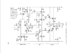
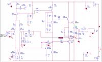
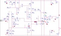
Thanks a lot for checking out my post, I really appreciate any help you can provide. I have been tasked with creating a blameless power supply, which is what I've done, according to the attached schematic. However the output doesn't match what the output should be by a long way.
I have a feeling I have made a mistake with the input of the schematic (How do I represent the NFB?) also PR1 is just a variable resistor that I've replaced with a regular resistor.
I have included my schematic, a copy of the output and a copy of what the output should be based on what I've been told, any pointers would be really appreciated, many thanks


