Continue to Site

Welcome to EDAboard.com

Welcome to our site! EDAboard.com is an international Electronics Discussion Forum focused on EDA software, circuits, schematics, books, theory, papers, asic, pld, 8051, DSP, Network, RF, Analog Design, PCB, Service Manuals... and a whole lot more! To participate you need to register. Registration is free. Click here to register now.

positive edge triggered D-flip flop....???

Status
Not open for further replies.

jawadali477

Member level 1
Joined
Dec 23, 2010
Messages
41
Helped
0
Reputation
0
Reaction score
0
Trophy points
1,286
Activity points
1,588
hi,
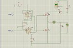
i'm working on laser range finder. the purpose is to charge capacitor for nano second time of flight. i'm using positive edge triggered D-flip flop. can some one help me how to control the D-flip flop to charge capacitor for the time of flight. the purpose is that the capacitor start charging when transmission starts and stop charging when transmitted pulse is received.

thanks.

jawad
 

How much of the design have you got? You need a start pulse to clock the flip-flop which will come from whatever triggers the laser, or from a comparator picking up the outgoing laser pulse. You then need a fast comparator to generate the stop pulse. You can then use the asynchronous reset to clear the flip-flop and trigger whatever is going to read the integrator value (presumably a micro). You need a fast, active, opamp based integrator.

Keith.
 

thanks Mr. Kieth
i have designed one circuit using HD74LS74 flip flop, switch transister 2N7000 and capacitor with some charging machanism, but the problem i'm facing is that the output state of the flip flop doesn't seem to change, its giving me 2V constantly. either its because of the fast switching but if it is, then it should give either the on state or off state not in between. isn't it so..???

jawad
 

yes, here it is. i have tried it on p-spice and on hardware to.
 

Attachments

  • cct.jpg
    cct.jpg
    224.5 KB · Views: 118

if you have better idea than this, please let me know. i really appreciate it.

thanks

jawad

---------- Post added at 23:52 ---------- Previous post was at 23:45 ----------

sorry, the cct was tested in proteus not in p-spice.
 

Where are you getting your start and stop pulses from? Are the the correct logic levels and the correct timing? One problem with your circuit is you are toggling both flip-flops but you have no means to reset the state. I would use one flip flip & use the start pulse to clock the flip flop and the stop pulse to reset it.

I am not sure the LM334 will be fast enough as a current source (nor the 2N7000 for that matter). Try just using one flip-flop and the output of that to drive an opamp based integrator.

What distance are you hoping to achieve?

Keith.
 

I am not sure the LM334 will be fast enough as a current source (nor the 2N7000 for that matter).
Neither they are. In addition, the configuration of Q1 seems questionable. It's working as a voltage follower.

You didn't tell about the intended tof resolution. But some more substantial high speed analog electronics has to be applied to get meaningful results. With profound knowledge of this discipline, you can design a time measurement circuit from the scratch, or you can try to understand and copy a known working circuit. But some input is needed for the design.

I would start with a differential pair as unsaturated current switch for the integrator input signal.
 

thanks for the concern.
what cct do you suggest for this method of time to amplitude converter.? the range i'm working on is 4 to 10 meters.

thanks

jawad
 

4 to 10 metres is not a good range for time of flight. The disturbance from firing the laser is tricky to eliminate. Phase shift method is better for those sorts of distances.

Keith.
 

hi,
can any one suggest me which current source and mosfet should i use for current mode time to amplitude converter??
 

Status
Not open for further replies.

Similar threads

Part and Inventory Search

Welcome to EDABoard.com

Sponsor

Back
Top