Continue to Site

Welcome to EDAboard.com

Welcome to our site! EDAboard.com is an international Electronics Discussion Forum focused on EDA software, circuits, schematics, books, theory, papers, asic, pld, 8051, DSP, Network, RF, Analog Design, PCB, Service Manuals... and a whole lot more! To participate you need to register. Registration is free. Click here to register now.

Pole Zero analyses in cadence

Status
Not open for further replies.

Junus2012

Advanced Member level 5
Joined
Jan 9, 2012
Messages
1,552
Helped
47
Reputation
98
Reaction score
53
Trophy points
1,328
Location
Italy
Activity points
15,235
Dear my Mentors,

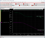
I am performing pole and Zero analyses for my amplifier, after simulation I saw a lot of poles and zeros which are not supposed to appear, I would be sure about it because my frequency gain loop is very clear behaving as single pole LPF,
I have enough phase margin so even the nearest pole to the GBW should be far.
While the pole zero simulation giving me some poles and zeros in my flat area.

May be my test bench and and simulation setup is not correct, could you please suggest me

Thank you in advance

- - - Updated - - -

I am connecting the amplifier in unity gain connection to have stable DC operating point,

I run only the PZ analyses with this setting

p1.png
p2.png
 

What is supposed to be the value of the max frequency in your second picture?
 
Dear friends tomorrow I will post the simulation result,

But the test bench setup is correct ?

Thank you once again
 

Hello

I would believe there is mistake either in the test bench setup or the simulation setting,

these are the result I got from AC and Pole Zero analyses

this time in the simulator I didn't sweep the frequency, I kept it constant

Any way, when I choosing the input source voltage for the setting, I am selecting the AC source

p4.png
p5.png
 

@Junus2012, are you afraid of poles and zeros? You're AC characteristic looks good. You have almost 80 degrees of phase margin and gain plot looks also nice.
 

No dear t4_V I am not afraid

But I want to learn how to see it from pole and zero analyses,

Otherwise in my graph, I can see clearly the first dominant pole and the first non dominant pole at the bend after the GBW
 

OK. Thank you for your reply. Now, I understand your query. I'm not into pole-zero analysis in Cadence, but isn't it that way that you look on poles on the left side of Y-axis. There you have 2 poles. Exactly, what is expected from AC characteristic as you wrote:

Otherwise in my graph, I can see clearly the first dominant pole and the first non dominant pole at the bend after the GBW
 

Can you zoom in around the x=0 axis? Your x-axis is in the units of THz and the very high frequency poles and zeros you see are some parasitics and I wouldn't worry about it too much. I am curious to see the low frequency parts.
 
Dear friends,

Thank you very much for your reply,

The simulator is giving the results in T Hz even when I tell him maximum 50 M,

There is some setting which I am missing
 

Status
Not open for further replies.

Part and Inventory Search

Welcome to EDABoard.com

Sponsor

Back
Top