Continue to Site

Welcome to EDAboard.com

Welcome to our site! EDAboard.com is an international Electronics Discussion Forum focused on EDA software, circuits, schematics, books, theory, papers, asic, pld, 8051, DSP, Network, RF, Analog Design, PCB, Service Manuals... and a whole lot more! To participate you need to register. Registration is free. Click here to register now.

Polarity of relay coil?

Status
Not open for further replies.
there is no polarity
 
  • Like
Reactions: treez

    T

    Points: 2
    Helpful Answer Positive Rating
its not like a solenoid then?
??? Standard solenoids are neither polarized. Some small signal relays however are polarized. And some relays have built-in freewheeling diodes, which also creates a polarity. In these cases, the polarity is clearly specified in the datasheet and mostly on the package.
 

    tpetar

    Points: 2
    Helpful Answer Positive Rating
    T

    Points: 2
    Helpful Answer Positive Rating

    deepmak

    Points: 2
    Helpful Answer Positive Rating
If i drive the coil of the 12V version of this relay from 24V, then is all i have to do is put a 1200R resistor in series with the relay's coil?
 

You will reduce current in coil which can result that coil dont have enough power to attract contacts.

For this solution should be more smarter than simple usage of resistor.


Best regards,
Peter
 
  • Like
Reactions: treez

    T

    Points: 2
    Helpful Answer Positive Rating
You will reduce current in coil

there will not be a reduction in current in the coil. The voltage is 24v instead of 12V. I did an ohms law calculation and the current is the same as it would have been with 12v.
 

Yes this will work, sorry I thought you want to run 24V relay on 12V.

Yes 1,2K resistor in serie with relay coil will have the same current in coil of 10mA.
 
  • Like
Reactions: treez

    T

    Points: 2
    Helpful Answer Positive Rating
BUT the start-up or initial current is different. You are looking at the locking or holding current.
 
  • Like
Reactions: treez

    T

    Points: 2
    Helpful Answer Positive Rating
BUT the start-up or initial current is different. You are looking at the locking or holding current.
I guess you didn't think about the actual effect. It's small, but strictly speaking the current of the series resistor supplied relay will setup faster, resulting in a slightly faster turn-on. If noticeable at all, it won't be unwanted.
 
  • Like
Reactions: treez and tpetar

    tpetar

    Points: 2
    Helpful Answer Positive Rating
    T

    Points: 2
    Helpful Answer Positive Rating
I guess you didn't think about the actual effect. It's small, but strictly speaking the current of the series resistor supplied relay will setup faster, resulting in a slightly faster turn-on. If noticeable at all, it won't be unwanted.

STRICTLY speaking, I do not see your assertment as valid whatsoever. ACTUALLY the resistor will inhibit the initial current rush and can easily prevent it from 'locking'. Turn-on would be slower, and even unsuccessful.

A resistor is UNWANTED - inhibits turn-on, slows turn-on and wastes power
 

the series resistor supplied relay will setup faster
..is this because the L/R time constant is less.

A resistor is UNWANTED - inhibits turn-on, slows turn-on
I see your point, but i have to use this relay for a test jig, its a 12V coil relay, and i only have 24V to drive the coil, so i must use a series resistor.

There is some debate now as to whether this relay will turn on faster or slower when the 12V relay gets used with a series resistor and a 24V input.

How will there be an inrush?......its a series LR circuit.
 

STRICTLY speaking, I do not see your assertment as valid whatsoever. ACTUALLY the resistor will inhibit the initial current rush and can easily prevent it from 'locking'. Turn-on would be slower, and even unsuccessful.

A resistor is UNWANTED - inhibits turn-on, slows turn-on and wastes power
To start with the point I agree with, of course a resistor wastes power. It will be only used in special cases, e.g. when a particular relays type isn't available or so.

Everything said about inrush current doesn't apply for standard DC relays. You might have thought about relays with AC coil, there are also some special relays with built-in electronic PWM driver that actually show an inrush current.

How will there be an inrush?......its a series LR circuit.
Exactly.
 
  • Like
Reactions: treez and tpetar

    tpetar

    Points: 2
    Helpful Answer Positive Rating
    T

    Points: 2
    Helpful Answer Positive Rating
http://www.nhp.com.au/files/editor_upload/File/TNL/NHPTNL54.pdf

http://www.toolingu.com/definition-460235-33963-inrush-current.html

**broken link removed**

http://www.global-download.schneider-electric.com/85257578007E5C8A/all/920D112ED83E08E5882575770009BBBE/$File/24572-en%20(web).pdf

**broken link removed**

http://www3.panasonic.biz/ac/e/control/relay/common/caugeneral.jsp

IF you read CAREFULLY you will see every manufacturer states there is a DC inrush current associated. The inrush current can be up to 10 times the holding current.

- - - Updated - - -

Everything said about inrush current doesn't apply for standard DC relays.

A common mis-understanding.
 
  • Like
Reactions: treez

    T

    Points: 2
    Helpful Answer Positive Rating
Despite of large load of paper you are calling as a witness, they don't say much not already stated in post #17. So you propably could have saved you some effort by reading more carefully.

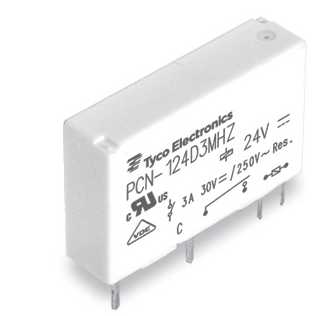
To remind the original thread topic, we are talking about small signal relays, particularly this one:

9545105500_1373372845.jpg


DC driven relays of this type never show an inrush current. As treez mentioned, there equivalent circuit is a L/R series circuit (with time variant L as a special point). Coil current is nevertheless monotonously risisng, which in other words means there can't be an inrush current. Believe it or not, but I've been measuring empirical relays and solenoid currents quite often when designing special startup circuits. You might want to check the result by solving the differential equation.

Off-topic in terms of this thread but interesting though, there are DC operated contactors with different behaviour. The Sprecher&Schuh application note puts the DC coil contactors into three categories:
- "True DC". Similar to the above shown relays, pick-up current = hold-in current (no inrush)
- "Two winding DC". Uses an auxilary contact disconnecting a high current auxilary winding. Respective inrush current
- "Electronic DC", already mentioned in post #17.

So we end up with what's already stated: There's no problem to use a series resistor to drop the voltage of a "True DC" relay or contactor coil.
 
Last edited:
  • Like
Reactions: tpetar and treez

    T

    Points: 2
    Helpful Answer Positive Rating

    tpetar

    Points: 2
    Helpful Answer Positive Rating
Status
Not open for further replies.

Similar threads

Part and Inventory Search

Welcome to EDABoard.com

Sponsor

Back
Top