Continue to Site

Welcome to EDAboard.com

Welcome to our site! EDAboard.com is an international Electronics Discussion Forum focused on EDA software, circuits, schematics, books, theory, papers, asic, pld, 8051, DSP, Network, RF, Analog Design, PCB, Service Manuals... and a whole lot more! To participate you need to register. Registration is free. Click here to register now.

PNP Transistor Current Basic Question

Status
Not open for further replies.

expelleior

Member level 1
Joined
Jul 25, 2009
Messages
40
Helped
1
Reputation
2
Reaction score
0
Trophy points
1,286
Location
OZ
Activity points
1,610
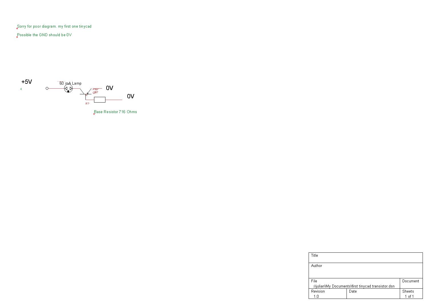
pnp transistor working

Forget 12V ;substitute 5V.

Using pnp transistor, if you have the collector connected to +positive 5V , then does connecting the base to ground with a suitable resistor allow current flow through the emitter and collector ?

So if the load, a LED draws 7mA and Transistor has an 100 HFE rateing then min base current = 7mA/100 HFE = o.o7mA

Base Resistor R1 = 5V /(7mA/100 * 1.3) the 1.3 is just to aqdd 30% to HFE
= 5V/ (7mA/130)
= 100 Ohms

And there is a 470 Ohmn reistor in series with the LED

Thanks for any help,
Mike.
70_1248909976.gif


Am I any where near close ?
 

pnp transistor basics

You say the collector of the PNP transistor is connected to +5V which is wrong, then show the emitter connected to +5V which is correct.

HFE is used for an amplifying transistor that always has plenty of collector to emitter voltage, not for a switching transistor that you want to saturate. The saturation spec for most transistors including the 2N3906 show a base current that is 1/10th the collecor current. So R1 should be (5V - 0.7V)/0.0007mA= 6143 ohms. Use 6.2k.
 

pnp transistor

Audioguru:

I was looking on the internet for calculation for a transistor as a switch, and a lot of sites uses HFE and the relationship Ic = HFE * IB to calculate the Base resistor:

IB = IC / HFE
Then RB = (VB - VBE) / IB

Can you show the documentation where it makes reference to 1/10th of Collector current ?

I would like to have it and compare.

I have always used the method explained above, but I would like to use the correct method (if it is different)

Thanks.
 

transistor basic

All transistor datasheets list the HFE (current gain) when there is plenty of collector to emitter voltage and no saturation.
Most datasheets list the maximum saturation voltage loss (you want it to be as low as possible) when the base current is 1/10th the collector current except the BC548 (1/20th) and 2N3055 (1/3rd).

From a batch of transistors a few have extra high gain and they will saturate with a lower base current.
The spec's are written to guarantee that all transistors in a batch pass the spec's, even the weaker ones.

Here is Philips' datasheet for the 2N2222 and 2N2222A:
 

basic transistor

Audioguru said:
The saturation spec for most transistors including the 2N3906 show a base current that is 1/10th the collecor current. So R1 should be (5V - 0.7V)/0.0007mA= 6143 ohms. Use 6.2k.

Thanks Audioguru, could you explain to me (5V - 0.7) ? The site I got the pic from said that this was a bipolar transistor and that you had to use HFE whish i was not sure what that was but you say I can use 1/10 of collector current which I accept.

thanks in advance.

Mike
 

pnp transistor list

There is a 0.7v drop across the PN junction.
 

pnp transistors list

I hope the png uploaded .

R1 = (5V - 0.7v) / .006 A

R1 = 716 Ohms ?

I used the switch component only because I couldnt draw a straight line. I'll fix it later :)

The load is a lamp drawing 60mA


current measurement for pnp transistor

Hello Expelleior,
You have the wrong type of transistor.
You saved your tiny sideways schematic as a fuzzy JPG.
Your resistor value is correct.

Note that a light bulb draws 10 times as much current when it is cool so the transistor must be rated for 600mA.
 

basic pnp transistor

Thanks! I used tinycad for the first time. Still working out which symbol means which transistor(but it probably said so when i chose it). And thanks for the tuition.
I am getting a multimeter and breadboards, components, relays etc today to start some experiments.

Thx again.
 

Since you have a positive supply voltage, the load is between the collector of the transistor and the posistive supply and the input is a positive voltage then you need an NPN transistor. It will not work if you use a PNP transistor.
Do you understand why?
 

hello everybody.I have exam and I need a quality question for bjt.do you have any document about transistors?ıf you have,can you share that.thx
 

Status
Not open for further replies.

Similar threads

Part and Inventory Search

Welcome to EDABoard.com

Sponsor

Back
Top