Continue to Site

Welcome to EDAboard.com

Welcome to our site! EDAboard.com is an international Electronics Discussion Forum focused on EDA software, circuits, schematics, books, theory, papers, asic, pld, 8051, DSP, Network, RF, Analog Design, PCB, Service Manuals... and a whole lot more! To participate you need to register. Registration is free. Click here to register now.

PM129A led panel meter problem

Status
Not open for further replies.

alexjes

Newbie level 4
Joined
Jan 14, 2012
Messages
5
Helped
0
Reputation
0
Reaction score
0
Trophy points
1,281
Activity points
1,317
Hi,

I have a led panel PM129A. It is showing at the first digit a "-1" and the other digits do not light at all, accept the decimal point. The meter is set up for 200 mV input measurement. After connecting the V- of the input channel to the gnd of the power suplly this error was showing up. No input is red any more. Afterwarts reading the manual I discouvered that the meter should have a independent powersupply.:???: It is not clear in the manual if i only can read independent inputs or that i must read indepent inputs. Are my strongest fears becumming true?:???: Did i blow up the fets of the input and is the 7107 CPL chip blown up, or is there some thing else wrong?:roll:

Regards,
Alex.
 

It clearly says that this is a single 9 Volts supply version of the meter. Means it needs separate 9 Volts supply to operate the meter and the you can measure the input. Did you read the manual before connecting it? Now make clear that when you connect the 9 volts supply does the meter display -1 and stays on with other digits blank? After your response further guidance may continued.
 

Yes I have red the manual before, but it was not clear that it was not possible to connect the input to the gnd of the power supply. Connecting it with a 9 Volt battery and the meter displays again -1 and the ohter digits stay blank.

Regards
Alex.
 

This shows over ranged input (the -1), which will cause the other digits to stay blank. It may have spoiled the input circuit. If you can check the circuit, then try to locate the circuit on PIN numbers 30 and 31. The input is given MINUS on pin 30 and PLUS on pin 31. See if there is any resistance divider or any other circuit apparently look bad. And if you have some experience on Diagram reading and following I can send you the circuit duly marked for check points.
 

Great! I can read diagrams. So if you point out where the problem is, then it will help me to clearify the problem.

Regards,
Alex
 

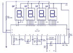
Ok here is a reference circuit for you. Please try to trace the input circuit and you will be definitely able to make it working with few question/answers.
7107.jpg
 

Thx, when I put 92 mV input on "V" and 0 V on IN, I measure on point V 92 mV and after R5 on the intersection with C5 82 mV and pin 31 of course the same. Pin 30 measures 0V.
When give a reverse input, pin 30 measures 92 mV and pin 31 0 V.
What can you conclude?

Regards,
Alex.
 

Pin 31 is positive input and pin 30 is 0 volt for INPUT circuit. While you connect 92 mV or so on input circuit, can you measure voltage on Pin 26. It must read minus voltage (estimated -5 V) and if this is true then I am afraid that 7107 is gone defective. If you short circuit the input terminals (going to pin 30 and pin 31) the reading must be zero and if this does not go to zero it meas there is some internal fault developed in 7107.
 

Pin 31 is positive input and pin 30 is 0 volt for INPUT circuit. While you connect 92 mV or so on input circuit, can you measure voltage on Pin 26. It must read minus voltage (estimated -5 V) and if this is true then I am afraid that 7107 is gone defective. If you short circuit the input terminals (going to pin 30 and pin 31) the reading must be zero and if this does not go to zero it meas there is some internal fault developed in 7107.

Pin 26 does not measure -5 V it is about 0 Volt. When I short cut the input, there is no effect on the reading. It stay's -1. The is tension drop of 10 mV over R5. So it means the input current is 10 mA. This looks also wrong.
I give up and buy a new chip.

Thanks for your help.
 

OK but better to be sure that there is no culprit on the existing board which may cause any problem for the new chip. I tried a lot to get the circuit for PM129 but sorry no reference found. But the circuit for 7107 is same for any brand only differs on the input circuit.
Good Luck.
 

Status
Not open for further replies.

Part and Inventory Search

Welcome to EDABoard.com

Sponsor

Back
Top