Continue to Site

Welcome to EDAboard.com

Welcome to our site! EDAboard.com is an international Electronics Discussion Forum focused on EDA software, circuits, schematics, books, theory, papers, asic, pld, 8051, DSP, Network, RF, Analog Design, PCB, Service Manuals... and a whole lot more! To participate you need to register. Registration is free. Click here to register now.

Pls help with this VCO design

Status
Not open for further replies.

ericyeoh

Member level 2
Joined
Jun 3, 2009
Messages
46
Helped
1
Reputation
2
Reaction score
0
Trophy points
1,286
Location
malaysia
Activity points
1,635
Hi all,

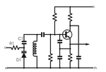
Really need help from u all. I've searched through the web, there were no topic teaching how to calculate all the component (Biasing resistor, colpitt frequency, coupling caps)value for below VCO design. This is the common model VCO pattern however i still cannot get it in detail.

Pls share me the detail If you guys hv relavent topic to this design. Thx :oops:
 

Attachments

  • VCO.png
    VCO.png
    5.8 KB · Views: 115

LC oscillators are finicky to get going.

It's hard to predict the right component values except in a general way. It depends on the characteristics of the inductor, the transistor, what is proper biasing based on surrounding circuitry, etc.

Then you need to adjust the bias to just the right point, so as to get the transistor operating between a small amount on and a medium amount on.

I've also seen more than one Colpitts configuration. (And more than one Clapp and Hartley types, etc.)

Seems there's not just one proper configuration. The avenue is open for experimentation and improvement.
 
Status
Not open for further replies.

Similar threads

Part and Inventory Search

Welcome to EDABoard.com

Sponsor

Back
Top