Continue to Site

Welcome to EDAboard.com

Welcome to our site! EDAboard.com is an international Electronics Discussion Forum focused on EDA software, circuits, schematics, books, theory, papers, asic, pld, 8051, DSP, Network, RF, Analog Design, PCB, Service Manuals... and a whole lot more! To participate you need to register. Registration is free. Click here to register now.

PLL with LM565, How does this circuit work?

Status
Not open for further replies.

hkBattousai

Advanced Member level 4
Joined
Jun 16, 2007
Messages
118
Helped
5
Reputation
10
Reaction score
1
Trophy points
1,298
Location
Turkey
Activity points
2,182
lm565

lab3fig3.jpg

**broken link removed**

I want to design a transmitter/receiver pair communicating via FSK modulation. I decided to design the transmitter side by a VCO. And I plan using LM565 on the receiver side.

At this point I need an explanation about the operation of the LM565 IC.
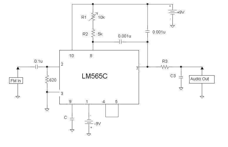
From my understanding (after half-an-hour search in datasheets and sample circuits on the web), this IC has two inputs; pins 2 and 3. The internal 'phase comparetor' consists of a product modulator and a low pass filter. The output of this LPF gives a voltage level which is proportional to the difference between the frequencies of these two input signals. We can probe this voltage level from the 7th pin of LM565.


I have two questions to ask :

Q1) Is my explanation above correct? Does LM565 really work as I explained, or operate in a different manner? Is there anything necessary to correct or add?

Q2) Can you explain me the function of the internal VCO of LM565? Can I leave the 4th, 8th and 9th pins not connected?
 

lm565 circuit

Qote: The output of this LPF gives a voltage level which is proportional to the difference between the frequencies of these two input signals. We can probe this voltage level from the 7th pin of LM565.

I didn´t go into details of the circuit, however, I like to make one correction:
The product detector creates an output signal which is proportional to the phase difference rather than to the difference of both frequencies. Nevertheless, pull-in of the PLL occurs also when both frequencies are different. However, this is a rather complicated non-linear process.
 

    hkBattousai

    Points: 2
    Helpful Answer Positive Rating
ic lm565

LvW said:
I didn´t go into details of the circuit, however, I like to make one correction:

The product detector creates an output signal which is proportional to the phase difference rather than to the difference of both frequencies. Nevertheless, pull-in of the PLL occurs also when both frequencies are different. However, this is a rather complicated non-linear process.

You say that the output voltage level is proportional with the phase difference. But how can you compare the phases of two signals if their frequencies are different? From my signal courses I remember that in order to talk about the phase difference of two signals their magnitude spectrum must be same.

And, I didn't understand what you meant by "pull-in" effect. I understand that it is related with the operation of the IC. Can you explain it please?
 

frequency difference circuit

hkBattousai said:
You say that the output voltage level is proportional with the phase difference. But how can you compare the phases of two signals if their frequencies are different? From my signal courses I remember that in order to talk about the phase difference of two signals their magnitude spectrum must be same.
And, I didn't understand what you meant by "pull-in" effect. I understand that it is related with the operation of the IC. Can you explain it please?

If both frequencies are not yet synchronized a so called "pull-in" action takes place, which simply means that the VCO frequency moves towards the reference frequency - under the condition, that the frequency difference is nor too large (this defines the "pull-in-range"). However, this is a relatively complicated procedure and there is no proportional relationship between this frequency difference and the control signal for the VCO. This is PLL theory and I cannot explain it here in detail. During this pull-in-process there are no phases which could be compared with each other. Only when both frequencies are nearly equal (when the PLL has locked) the phase difference mainly determines the control voltage and can cause synchronization.
It is important to know that the above mentioned applies to a product detector, which you are going to use.
There are other detectors (Phase-Frequency Detector, PFD) which are able to react upon frequency differences with a proportional control voltage.

Added after 12 minutes:

Perhaps I should explain the pull-in process in more detail:
If you multiply two different frequencies a term exists which contains the frequency difference and the phase difference. Thus, the control signal is modulated with a signal which roughly is identical to the frequency difference, but it is NOT sinusoidal (important !). This modulating signal is unsymmetric and has a mean value which moves the VCO towards the reference. As a consequence, the frequency of this modulating signal decreases. It is a highly non-linear process.
And therefore, the linear PLL model applies only when this process has come to an end (when the PLL has locked), and only then the phase difference comes into the play and keeps the PLL in this synchronized condition
 

    hkBattousai

    Points: 2
    Helpful Answer Positive Rating
lm 565

The integrated circuit has a VCO as well as a phase detector because they are usually used together to form a demodulator. This chip is intended to work with < 1 MHz signals.

You form a linear control loop with the onboard VCO and phase detector, and some off chip R's and C's. In this case the VCO drives one of the phase detector inputs. The other phase detector input is driven by an external source (once again < 1 MHz).

As the external signal sources frequency SLOWLY moves up, for instance, the onboard VCO will sense an instantaneous phase error between its two inputs, and automatically try to correct the phase error. As a consequence of trying to correct this error, the onboard VCO frequency also tracks higher in frequency--trying to keep the onboard VCO in phase-lock to the external source. If you monitor the tuning voltage going to the onboard VCO, you can crudely guess the external source's frequency by simpliy measuring the tuning voltage.

Of course, if the external source frequency moves too far or too fast, the control loop will not be able to keep up. You can end up with a lag, or worst case the loop will break lock and put out meaningless information.

Kind of a crude way to do things!
 

    hkBattousai

    Points: 2
    Helpful Answer Positive Rating
how does a pll work

What I didn't understand is, the phase comperator must have only two inputs, but inside of LM565 there are three inputs for it :

1) Input 1 (Pin 2)
2) Input 2 (Pin 3)
3) Output of internal VCO (Pin 5 to pin 4)

Can you tell me which of these three are the actual inputs of the phase comperator?
 

lm565 ic

The VCO output comes out pin 4, and you send it to the phase comparator by bridging to pin 5.

Pins 1 & 2 are a differential input for the other phase comparator input. It looks like they use pin 1 as a single ended input, and ground pin 2, for most applications. It looks like there is NOT a frequency detector portion for the phase detector, so the lock-in range is limited.
 

    hkBattousai

    Points: 2
    Helpful Answer Positive Rating
lm565 pll

Of course, actual inputs are pin 2 and pin 3.
Pin 4 and 5 are connected in order to feed the detector output to the VCO input.
However, if you like (or if its necessary) you can place a filter in between.

Added after 35 minutes:

Hi hkBattousai,

as you were interested in the pull-in action, attached please find a pdf document showing this process as a simulation result. I think the figure is selfexplaining.
But if you have questions, send a reply.
 

    hkBattousai

    Points: 2
    Helpful Answer Positive Rating
lm565 vco

This is just to correct a small error in the pdf file posted above:

The real input reference frequency is 54 kHz (instead of 55 kHz as indicated in the block diagram)
 

    hkBattousai

    Points: 2
    Helpful Answer Positive Rating
Status
Not open for further replies.

Part and Inventory Search

Welcome to EDABoard.com

Sponsor

Back
Top