Continue to Site

Welcome to EDAboard.com

Welcome to our site! EDAboard.com is an international Electronics Discussion Forum focused on EDA software, circuits, schematics, books, theory, papers, asic, pld, 8051, DSP, Network, RF, Analog Design, PCB, Service Manuals... and a whole lot more! To participate you need to register. Registration is free. Click here to register now.

PLL Loop filter values for FM

Status
Not open for further replies.

geotFM

Junior Member level 3
Joined
Sep 19, 2017
Messages
29
Helped
0
Reputation
0
Reaction score
0
Trophy points
1
Activity points
276
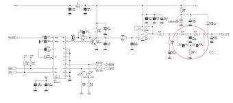
Hello.I have this PLL loop filter around Tsa5511 and i have some questions.
What is the role of the circuit after uA741?
I also have an almost same circuit but with different values for the parts inside the red circle.
R26,R27=1K5
R28=680
C32=200nF
C33,C34=100nF
Which of the values perform better?
Thank you.
 

Attachments

  • pll1g.jpg
    pll1g.jpg
    735.7 KB · Views: 229

An almost useless notch filter, because C46 attenuates components at the notch frequency (about 6 kHz) already by 90 dB.
--- Updated ---

1642082093422.png
 

The modified double-T parameters shift the notch to 1 kHz, but the 10 uF capacitor is still shorting the output. Maybe it has different cpacitance too.
 

Hi,

the phase comparator works at 6.25kHz, maybe the goal was to suppress it´s fundamental.
But with the value of C46 it makes not much sense.

Klaus
 

The sims seem to indicate, even with the 10u at output of twin T, lots of suppression -

1642095257664.png


But using reference the slope of the projected LPF response, from that slope only about 14 db...
Does make one wonder why the Twin T in the presence of a dominant LPF....

If the 10u goes away the notch has a dramatic effect as one would expect. But LPF
now gone for other freqs.

1642095902799.png


Regards, Dana.
 
Last edited:

Hello and thank you all for answering.Looking at the datasheet of TSA5511 the reference frequency of the phase comparator derives from the frequency of the external crystal divided by 512 so for a crystal of 3.2MHZ the reference frequency is 6.25Khz as you said so the values of the first schematic i posted make sense (except for the C46=10uF)

The modified values
R26,R27=1K5
R28=680
C32=200nF
C33,C34=100nF
give the T-notch a frequency of around 1Khz

I have two schematics of a pll loopfilter both using 3.2MHZ crystal at the TSA5511 but one with aTnotch frequency around 6.4Khz and the other with a T-notch frequency of 1KHz and no 10uF capacitor.I also attach the VCO i am going to use.

So the best is to stick with the values that give a frequency of around 6.4Khz?
 

Attachments

  • TSA5511fref.jpg
    TSA5511fref.jpg
    1.3 MB · Views: 170
  • tsa5511 fm loop filter.gif
    tsa5511 fm loop filter.gif
    37.2 KB · Views: 160
  • pll1g.jpg
    pll1g.jpg
    735.7 KB · Views: 152
  • PLL2G.jpg
    PLL2G.jpg
    664.1 KB · Views: 171

Any particular reason why you are not using a 150nH inductor instead of a 18cm RG178 coax cable?
 

Hello.I dont know why the designer uses 18cm RG178 coax cable instead of a coil.its not my design.Maybe it has better stability than a coil since its inductance doesnt change when you get close to it.

The oscillator is tested and working.
Another point i dont understand is the use of the resistor R19=470K in parallel with C24=47uF capacitor at the audio input section.
 

Theoretically is no need for R19, but I think that R23, R21, R19 and P1, all together forms a DC voltage divider, need to DC bias the D28, D26 varicaps, which are used for FM modulation.
 

Status
Not open for further replies.

Similar threads

Part and Inventory Search

Welcome to EDABoard.com

Sponsor

Back
Top