Continue to Site

Welcome to EDAboard.com

Welcome to our site! EDAboard.com is an international Electronics Discussion Forum focused on EDA software, circuits, schematics, books, theory, papers, asic, pld, 8051, DSP, Network, RF, Analog Design, PCB, Service Manuals... and a whole lot more! To participate you need to register. Registration is free. Click here to register now.

PLL FM transmitter 300mW RDVV problem

Status
Not open for further replies.

driverbulba

Newbie level 6
Joined
Apr 6, 2012
Messages
14
Helped
0
Reputation
0
Reaction score
0
Trophy points
1,281
Activity points
1,399
First post here! Nice to meet you!

I recently made the pll fm transmitter 300mW Rdvv as it is here: https://www.3-mtr.info/shareware/RDVV%20300mWatt/

The pic, the buttons, the lcd are working perfectly! However the TSA5511 chip gets extremely hot and the PLL cannot lock.

I found out that it is not an oscillator problem, as the vco part itself oscillates! I also found out that the reason why TSA5511 chip gets hot is the pin11 which connects to the base of BC557..

Definitely it is not a hex and programming problem because I've tried more than 3 hex files and my programmer works great! Besides LCD works!

Why does this happen and how can I solve it?

Thank you!
 

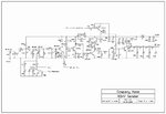
There is not a circuit diagram, only the pcb and where each component is soldered...

Can't find out what's the problem.....
 

**broken link removed**

The BJT placed at the charge pump output may be dead or wrong connected, and a higher voltage goes to the PLL output. Or there is a collector resistor with wrong value (smaller than should be).
 

Thank you everyone for your answers!

A friend took my multimeter till tomorrow so I can't measure the voltage at pin. 11 right now.. However I'll check it tomorrow
Which transistor do you think that it's burnt?

I tested a few more things today. At first, I unsoldered the BC557 transistor from the pcb to test the circuit's behaviour. Now the TSA5511 does not get hot at all, but the 78L09 just above the variable resistor gets extremely hot now..

After discovering that, I unsoldered the BD139 transistor, the 22K resistor above the BC557 but the 78L09 was still hot.

When I unsloldered the 10 ohms resistor that is connected to the output of the 78L09, the 78L09 stopped getting hot...

Can you imagine what causes this strange behaviour?
 

Hi anilrock87! Generally I use Eagle, but I didn't design this one myself.. I found it on the internet! :)
 

I finally got my multimeter back and measured the voltage at the pins of the TSA5511.

I get ~5V at pins 6,7,8,9,10,11,12,13!! This behaviour can't be normal! Why does this happen?

The leds stay off and the 78L09 gets hot because of this.

1) Does this mean that the TSA5511 does not communicate with the PIC?
2) Or the TSA5511 is burned?
3) Or is it a mistake in the circuit

Thank you :)
 

You need a circuit diagram. Is it the same as the one posted above (**broken link removed** )? Because you mentioned a BC557, but I couldn't see any PNP transistor..
You've mentioned some component values, but without a diagram it is very hard to diagnose.. Maybe take a detailed photograph of the
board which you've soldered, which shows the colors of the resistors too?
 

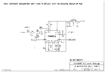
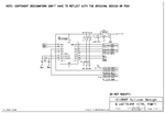
rdvv-2006v6-pic16fxxx-schematic.gifrdvv-notune-2006v6-8watt-schematic.jpgrdvv-notune-2006v6-pll-tsa5511-schematic.gif

This circuit diagram is what I am using.. But the output stage with 2SC1971 is different for me, I don't use this transistor, my version is slightly different.
Everything is almost the same, instead of the transistor in the oscillator stage. I use BF981.
 

Ok, so focussing on one thing at a time; if your 78L09 is hot, then there are really only a few things that could be wrong.

1. You're not supplying 13.8V, and the voltage is higher, or is reversed (easy to check with the multimeter)
2. The 7809 has been soldered in backwards or a pin is shorted or something (check with the continuity mode, unpowered)
3. One or more of the resistors that are connected to pin 3 of the 78L09 (as shown in the diagram)
are the wrong value

Can you measure the resistors with your multimeter and confirm the values? (or check the
color codes, but sometimes they are not easy to read).
You need to unsolder one wire of the resistors, that is easy if you use a small screwdriver to gently lift one
end of the resistor while heating the wire with the soldering iron.

Also, can you take a detailed color photo of both sides of your board, and post it? In case we can read and
confirm the color codes?

EDIT: by they way, I just noticed you said:
When I unsloldered the 10 ohms resistor that is connected to the output of the 78L09, the 78L09 stopped getting hot..
However, the circuit diagram doesn't have a 10 ohm resistor connected to pin 3 of the 78L09. So the board seems to be
different from the circuit diagram.
Can you scan or take a photo of the instructions too, as well as the photo of your soldered board, both sides?
 
Last edited:

Hi
how can i compensate 90 degree phase shift in pll?
 

sky_123 thank you for your answers! :)

When I remove the TSA5511 from the board, the 78L09 supplies 9 volts without getting hot.
If I put again TSA5511 on the board, the 78L09 supplies now ~4 volts on its output, so it gets hot!

However, if I don't solder the pin 10 of the TSA5511 on the board (this pin is connected directly to ground), the 78L09 stops getting hot!

My explanation is that the output of TSA5511 on pin 10 is high (~5 volts, I measured it with the multimeter) continuously, and it is directly connected to ground, so we have a short circuit here! (That's why I measure 3,6 amperes!!!)

Finally, this happens to EVERY output port of the TSA5511... Every output port is ~5 volt, which is the reason why LEDS stay off.................

Now, what should I try...?
 

According to the diagrams, the 78L09 doesn't interact with the TSA5511. Do you mean the 78L05 is getting hot? (The 78L05 is marked
as IC2 on the diagram.
Since you mentioned a 10 ohm resistor connected to the 78L09 earlier, I suspect the circuit is very different from the diagrams. This means
it is next-to-impossible to diagnose the issue, because I can't see which component is wired to which component. It is like
trying to fix a car blindfolded (and not knowing the make of the car either).
Basically, more information is needed. Does the documentation say that a 10 ohm resistor should be connected to the 78L09?
If so, can you supply all the information that came with the kit? And ideally a photo of the PCB (both sides) so that the traces
can be followed.
 

OK, this may help you: COMO.png

This is the exact board I made. The output of 78L09 is connected to a 78L05 which supplies the TSA5511.. So there is a connection between 78L09 and TSA5511.

However, let's just forget the 78L09 problem, because it is solvable if I don't ground the pin 10 of the TSA5511.

The main problem is that all the outputs of TSA5511 are high (~5 volts).... And at pin 18 I have 0 volts. So there is always 9 volt at the varicap!
 

Ok, the diagram helps.
I think it is expected for the 78L09 to get a warm if you're running at 13.8v and it is powering the circuit that is powered through the
78L05. However, I don't think it should be too hot.

Pin 10 is an I/O pin, i.e. it can be configured for input or output by the PIC. It could be that disconnecting it is ok. However, what if it
was intended to be configured as an input by the PIC, and the software checks that the pin is low? (Unlikely, but possible - sometimes people use
I/O pins to act as hardware configuration settings inputs).
Anyway, it is worth checking a few things. Firstly, the circuit diagrams are definitely incorrect - they show the TSA attempting to power LEDs
in an odd manner that won't work (I see that is corrected on the board though). Secondly, the diagrams (and the circuit board) show a 100 ohm
resistor connected to the oscillator reference voltage pin 3 and to 5V. However, the datasheet doesn't show that. It could be a fault, or could be ok.
The only way to know for certain is to stick an oscilloscope on pin 2 and see if there is an oscillation. You need to get access to a scope to
do that - a multimeter can't do this.
If there is no oscillation, then this would be a very good cause for the TSA output (pin 18) to be low.
Also, don't rule out the PIC. Are you 100% sure that it has been programmed with the correct program?
If it hasn't, then definitely this could cause the output to be low.
I suspect you may need to contact the kit developer and ask them for the correct software for the PIC,
to match your circuit.
So, in summary, you do need to get some time with an oscilloscope to confirm that the oscillator is functioning.
And double-check the PIC software is correct for your board.
 

There is an oscillation there, as I measured, so everything is ok here.
Furthermore, I've tested 5 different hex files that are available for this project, and every program has the same behaviour.

This is interesting: When I first connected the project to power supply, the RED led turned on! So the pin 9 of the TSA5511 was pulled low!
However, the TSA5511 was getting extremely hot...

After some tests, the led stopped turning on....

So, I've started thinking that maybe the TSA5511 chip is burned or destroyed.

Is it a possible cause?
 

Yes, if the behavior has changed, then you should suspect that something as been destroyed unfortunately in this case : (
ICs can handle a fair amount of heat, but I noticed you mentioned 3.6A. This is a huge amount of current.

However if there are oscillations there, then it may be ok, or it may have partially failed. The TSA is instructed to do things via
the SDA and SCL lines. Those lines need some equipment to confirm (e.g. oscilloscope). However if the kit vendor is reputable then the
PIC should be correctly programmed to supply the correct data over the SDA and SCL lines.

It looks like you're considering the correct steps (e.g. try a new TSA). To save costs, try to insert a low value resistor (10 ohms will be a
good choice) in series with the supply pin to the TSA, to reduce the risk that another TSA gets accidentally damaged. That will
protect the TSA chip.

Once you've got the new chip in there, it may be worth disconnecting the 100 ohm resistor from pin 3, just in case that is incorrect
(the datasheet really doesn't mention the need for this).
 

Today I was told that PIC16f628A has problems with portA as digital output, and maybe this is the reason why it doesn't communicate with the TSA5511...
Should I try with the PIC16F628 04/P ? What are the differences?

The project has also 3 hex files for PIC16F84.....
 

Status
Not open for further replies.

Part and Inventory Search

Welcome to EDABoard.com

Sponsor

Back
Top