Continue to Site

Welcome to EDAboard.com

Welcome to our site! EDAboard.com is an international Electronics Discussion Forum focused on EDA software, circuits, schematics, books, theory, papers, asic, pld, 8051, DSP, Network, RF, Analog Design, PCB, Service Manuals... and a whole lot more! To participate you need to register. Registration is free. Click here to register now.

PLL control voltage changes

Status
Not open for further replies.

Bryan79

Newbie level 5
Joined
Oct 17, 2004
Messages
8
Helped
0
Reputation
0
Reaction score
0
Trophy points
1,281
Activity points
137
causes fordead zone in pll

Hi, I have designed a simple PLL circuit using PFD, 3rd order type type 2 filter, a charge pump and a ring oscillator type VCO.

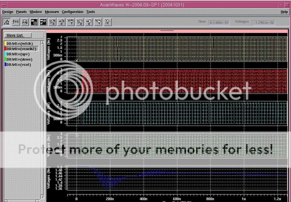
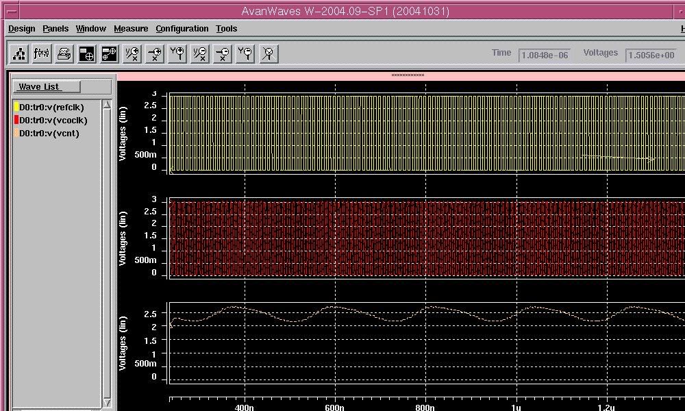
I notice the control voltage (vcnt) of VCO oscillates and cannot settle down.

Anyone know any idea what is wrong? I have tried to make my charge pump current matches, eliminate dead-zone in PFD by adding delay to reset path and adjusting the R,C of the filter. But it still gives me oscillating control voltage.

pllwave.jpg


Thanks.
 

pll control

It is possible that entire loop isn't stable enough. Did you do some calculation before?
 

Is the Phase Margin of your filter large enough for stability?
Do you have the Open loop response of your filter?
The reason that you are using Type-2 filter starts the phase at -180° and integrator of the VCO decreases that to -270°, so if position of the zero is not accurate enough you might run into a situation where your phase margin is very low, resulting in such unstable Vcnt of VCO..

If your specification for Spuirous response are lineant...try using Type-1 Second Order filter...

Regards
 

zajbanlik said:
It is possible that entire loop isn't stable enough. Did you do some calculation before?

Er... i did some calculation and the phase margin was like 55 degree.

I am using a filter with series R2 and C2 , and parallel with C1.

R2 = 17.4 kOhm
C2 = 7 pf

C1 = 0.5 pf

Added after 3 minutes:

my charge pump is 19 uA, so I guess Kpd = Ip/2pi

my VCO gain is 48.67 MHz / V.
 

I just saw the components you mentioned...you are missing 1 resistor and capacitor if the filter is 3rd order as you mentioned in your first post...!!!

am i missing something??

Regards
 

Bryan79 said:
zajbanlik said:
It is possible that entire loop isn't stable enough. Did you do some calculation before?

Er... i did some calculation and the phase margin was like 55 degree.

I am using a filter with series R2 and C2 , and parallel with C1.

R2 = 17.4 kOhm
C2 = 7 pf

C1 = 0.5 pf

Added after 3 minutes:

my charge pump is 19 uA, so I guess Kpd = Ip/2pi

my VCO gain is 48.67 MHz / V.
Well in linear model it should be ok, then it is probably with the filter.
like haadi20 said.
 

haadi20 said:
I just saw the components you mentioned...you are missing 1 resistor and capacitor if the filter is 3rd order as you mentioned in your first post...!!!

am i missing something??

Regards

Er.. i think the filter is 2nd order, but the open loop response G(s)H(s) is 3rd order because Kvco / s of VCO adds another s to the denominator.

I have a feeling may be it is due to the little mismatch of charge pump current. This is because I remembered that if I put in a same 60MHz clock signal to the 2 inputs of the PFD, the VCO outputs a 62 MHz clock (i.e, I didn't connect VCO output to the input of PFD, in other words, no feedback, not a closed loop system, but a open loop system).

I think I will try to run simulation again on Monday by subsituting the charge pump by IDEAL current sources.
 

Hi :

If the parameters are right for PLL linear model :
How about your PFD output signals (eg up / down), are they stable in a
constant level or not , when VCO output the your desired signal(frequency) ?


mpig09
 

Decrease R and increase the caps. The amplitude of the error is adequate to R size and current through it.
Check the PFD for dead zone (run transient sim in conservative from -2ps to 2ps by 0.1ps)
Go to higher order filter
And try to increase the comparison freq (the one going to pfd)
 

what

.4v varience over a 200ns window

treat the control voltage in single frame's


i think .4 v over this time is a big parasitic oscillation


looks like stray capacitance it is the cause of this

in a real circuit youll get this wobulation

and more just as a result of microphonics

in the hysterisis of the circuit as a whole

looks like overall your not getting cap leakage of unwanted signals {decoupling}
rather than coupling judging by the time frame

i think .5pf is a really small value and an inherrant unstable choice

stick to 3.3pf and adjust
 

I would like to thank all people who helped to give suggestion.

Apparently, I found out it was my mistake. The resistor model for R2 that I used in the filter didn't appear in the netlist. That means it is an open circuit for the series R2 and C2 part. What is left effectively is just the C1 = 0.5 pF. No wonder, the PLL cannot work.

Now, the waveform seems much nicer.

pllwave2.jpg
 

your BW maybe 1/15 ~1/10 of you comparison frequency. u can try it.
 

Status
Not open for further replies.

Similar threads

Part and Inventory Search

Welcome to EDABoard.com

Sponsor

Back
Top