Continue to Site

Welcome to EDAboard.com

Welcome to our site! EDAboard.com is an international Electronics Discussion Forum focused on EDA software, circuits, schematics, books, theory, papers, asic, pld, 8051, DSP, Network, RF, Analog Design, PCB, Service Manuals... and a whole lot more! To participate you need to register. Registration is free. Click here to register now.

Please help to identify the signal input port on board

Status
Not open for further replies.

koreansud88

Newbie level 5
Joined
May 22, 2022
Messages
10
Helped
0
Reputation
0
Reaction score
0
Trophy points
1
Activity points
142
To whom it may concern

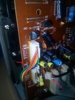
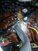
I am repairing a 18 year old stereo player from Orion, of which the mp3 and USB player does not functional. The main board is shown in the attached photos and my intention is to find the signal input port on said board, allowing the connection to a 3.5mm jack plug cable. Due to the complexity of its internal cable, the circuit board is hard to be dissembled. Any advice will be appreciated. Thank you in advance.
IMG_20220522_164239.jpg
IMG_20220522_164227.jpg
IMG_20220522_163557.jpg
 

Solution
The source selector is probably the spot to attach your new cable. At the CD or tape position.

The source selector might be a rotary switch, or several switches in a row interlocked so that just one at a time is activated.

Examine wires at the CD or tape position. Maybe it's obvious which wires carry audio. If it's not obvious, then touch the contacts while the system is powered up. When you find the right wires you hear hum from the speakers.

Do you have jumper clips? Try a test hookup. Identify which channel is left & right. Solder your new wires there.

You must also solder the ground wire. There ought to be a choice of nearby places on the board.
Does the unit let you switch among audio inputs from external devices? Such as Aux, Line-In, CD, VCR, Tape, etc.

Then I imagine an adapter cable is all you need. 1/8 inch stereo to 2 phono plugs.
 

Thanks, yes, there are switches between CD, Tape, Radio and USB. Unfortunately the USB does not work. Would you please help to spot out which two mount ports on said board, allowing me to connect 3.5 mm Jack cable? Thanks in advance.
 

USB is digital data, not analog audio. Without USB you might as well use your existing analog inputs (CD, tape). Does your MP3 player produce audio output?

Your board appears to be all-in-one. I can't recognize where left and right audio feed into the final amplifying IC. It may be within copper traces rather than wires.

Besides, if you solder your own wires to them, it's liable to introduce hum or other unwanted noise.

Then you must also find a way to disconnect other audio signals.
I believe such switching is already built into the unit via the CD & tape selectors? Or if these are in use then you can always add an external input selector.


external audio source selector.jpg
 

USB is digital data, not analog audio. Without USB you might as well use your existing analog inputs (CD, tape). Does your MP3 player produce audio output?

Your board appears to be all-in-one. I can't recognize where left and right audio feed into the final amplifying IC. It may be within copper traces rather than wires.

Besides, if you solder your own wires to them, it's liable to introduce hum or other unwanted noise.

Then you must also find a way to disconnect other audio signals.
I believe such switching is already built into the unit via the CD & tape selectors? Or if these are in use then you can always add an external input selector.
Thanks for your thorough reply.

It is a Orion MCT 1563 Unit, https://www.amazon.de/-/en/Orion-MCT-1563-Unit/dp/B000E8M18C and I tried to fix it for a 70 year old retired neighbor - Oliver. His grandson tried to convince him to replace the Orion by a tablet, but Oli prefers the old one - reduce the waste for environment. All his wanted is to connect a 3.5 mm jack cable to its amplifier INPUT signal port, enabling the stereo system to play mp3 signal from his smartphone.

Would anyone please help to identify said input port on board?

Noise is acceptable. The CD and tape is on separated board. I have disconnected all wire but the main board shown in photo is fixed on the package. I cannot see the opposite side the board. Therefore, I was writing to request your experts elegant advice to find the two input signal. Cheers.
 

The source selector is probably the spot to attach your new cable. At the CD or tape position.

The source selector might be a rotary switch, or several switches in a row interlocked so that just one at a time is activated.

Examine wires at the CD or tape position. Maybe it's obvious which wires carry audio. If it's not obvious, then touch the contacts while the system is powered up. When you find the right wires you hear hum from the speakers.

Do you have jumper clips? Try a test hookup. Identify which channel is left & right. Solder your new wires there.

You must also solder the ground wire. There ought to be a choice of nearby places on the board.
 

Solution
The source selector is probably the spot to attach your new cable. At the CD or tape position.

The source selector might be a rotary switch, or several switches in a row interlocked so that just one at a time is activated.

Examine wires at the CD or tape position. Maybe it's obvious which wires carry audio. If it's not obvious, then touch the contacts while the system is powered up. When you find the right wires you hear hum from the speakers.

Do you have jumper clips? Try a test hookup. Identify which channel is left & right. Solder your new wires there.

You must also solder the ground wire. There ought to be a choice of nearby places on the board.
Many appreciate your kind response.

The CD out signal cable was found which connects the CD PCB to the main PCB board. I have tried to connect a 3.5mm jack cable to the mainboard, of which the output signal does not seem to be amplified highly enough to drive the speaker. A coarse measurement on the LGR output signal from CD board is at approximately 1.8V while the signal from 3.5mm jack cable is niche.

The source selector is not a mechanical switch but for an ASIC chip on the back of display PCB. As switched by a button, it presumably triggers a sequence look-up table or flipflops in said ASIC. There is few things could be fiddled on the source selector unfortunately.
 

Attachments

  • IMG_20220524_163429.jpg
    IMG_20220524_163429.jpg
    344.4 KB · Views: 161
  • IMG_20220524_163453.jpg
    IMG_20220524_163453.jpg
    435.3 KB · Views: 165

USB and MP3 signals are digital. They must first be converted to analog then they will follow the same path as the CD, etc. signals. That would indicate that your converter isn't working. Connecting a 3.5mm jack to the USB or MP3 input ports isn't going to help anything. With very clear pictures of all the boards and the silk screen and a clear picture of what you want to accomplish, one may be able to figure something out for you.
 

Status
Not open for further replies.

Part and Inventory Search

Welcome to EDABoard.com

Sponsor

Back
Top