Continue to Site

Welcome to EDAboard.com

Welcome to our site! EDAboard.com is an international Electronics Discussion Forum focused on EDA software, circuits, schematics, books, theory, papers, asic, pld, 8051, DSP, Network, RF, Analog Design, PCB, Service Manuals... and a whole lot more! To participate you need to register. Registration is free. Click here to register now.

[SOLVED] Please help to check whether a pickit2 schematic is correct

Status
Not open for further replies.

aravindj36

Junior Member level 1
Joined
May 11, 2011
Messages
15
Helped
1
Reputation
2
Reaction score
1
Trophy points
1,283
Location
Kochi,Kerala,India
Activity points
1,382
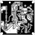
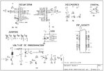
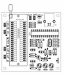
Hello there ,I'am planning to make a Pickit-2 clone.While googling I found a lot of schematics for the same.But I noticed that most of the circuits of the clone which comes from trusted sources have upto 7 transistors and use a680uh inductor.When I enquired in my local electronics shop they said that they dont stock any inductors.Thats when I saw the schematic of a clone which uses just 4transistors and no inductor.Iam planning to make this but Iam not sure whether the schema is correct.Could someone help me know whether the schema is correct.I have attached aView attachment Programmerschematic.pdf .pdf file of the schematic.I just wannabe sure that the schema works before buying the components it is because I have heard stories of pics being damaged due to small errors in the schematic.
 

Inductor is used for generating 13 volts from 5 volt usb supply. It is reqired for "high voltage programming". Microcontroller (not all) can be proagrammed through low voltage programmeg LVP using 5V of USB.
You have to source 18f2550 or18f4550 also. Inductor is not critical, can be 470u or 820u. Ie fint can be sourced from old tv or monitor kits if you visit tv mechanic workshop. They keep these kits to pull out and use components reqired.
I am also going to make one. I'll show what schematic i have finalizd.
 
Thanks for yhe quick reply.I could get the 18f2550 from a shop but I could not find the inductor anywhere.Iam planning to assemble the given schema because it has only 4 transistors.Hope you post your schematic soon.
 
I personally use Microchip's ICD2, ICD3 and Real ICE for all my PIC debugging/programming needs, so I can offer little opinion concerning a PICkit2 clone design.

However there has been several length discussion threads concerning PICkit2 design which you may find helpful.

Including the following example:

"PICkit 2" DIY(Do It Yourself) fans

BigDog
 

prooven to work pic kit 2 clone, works for 5v AND 3v pics...
**broken link removed**
regards,
 

On first sight, the "VPP generation circuit" shown in the initial post is simply absurd. Reviewing it more thoroughly, it uses capacitor symbols representing an inductor. If you don't noticed that's something wrong with the circuit, take it as a pretty strong hint to better buy a ready made PIC programmer.
 
Um Im sorry for the mistake.Only now when I checked the circuit again I noticed that they were Inductors drawn with the symbol of capacitors.

Today I saw the schema of a gtp usb lite it uses just capacitors and a handful other components to generate the 13v.Is there someway I can get the pk2 firmware into a gtp usb lite.It might seem mad but I remember reading somewhere that it is possible.
 

If it can be made with less than half a price including zif socket. Second most important where in world you can't source a coil, how you can manage to buy from ebay.

I dont think the hour needed to build it if you already own the components is worth less than $20 ... even in china !
also the hourS needed to debug it if you're a beginner and find your cold soldiers...

---------- Post added at 18:21 ---------- Previous post was at 18:20 ----------

Today I saw the schema of a gtp usb lite it uses just capacitors and a handful other components to generate the 13v.Is there someway I can get the pk2 firmware into a gtp usb lite.It might seem mad but I remember reading somewhere that it is possible.
this won't work ...
 

I dont mind some extra cost unless i get full plans especially neat single sideed pcb artwork which i can make at home.
I think i am gonna make this.
 

Attachments

  • PCB.jpg
    PCB.jpg
    54.1 KB · Views: 117
  • SCH.jpg
    SCH.jpg
    564.1 KB · Views: 130
  • placement.jpg
    placement.jpg
    30.2 KB · Views: 118
  • pickit2_clone.zip
    908.9 KB · Views: 137
Last edited:

the best circuit is by Palma
**broken link removed**
the zif socket is right on the pcb and it works great !!
Translate the page from Spanish to English with translate.google.com
No need to search for a 680uH inductor, make one yourself
get a color TV IF coil and remove its windings and then wind approximately 120 turns with 31 SWG copper enamelled wire
it may not be exactly 680uH but it works all right
good luck !!
 
Last edited:

TV IF coil and remove
There is a underlying capacitor. Remove it also although it does not make much difference.
Another way to make your own coil found in another thread.
As for 680uH inductor. Which I couldn't find in my country (Croatia).
I used a small toroidal core (gray green color) from compact fluorescent lamp (CFL) and wound 16 turns of 0.5mm emailed copper wire. :)

Toroid core has dimensions approx:
d=3.6mm
D=8.4mm
w=4mm

My LC meter showed about 660uH :)
 
Last edited:

Status
Not open for further replies.

Part and Inventory Search

Welcome to EDABoard.com

Sponsor

Back
Top