Continue to Site

Welcome to EDAboard.com

Welcome to our site! EDAboard.com is an international Electronics Discussion Forum focused on EDA software, circuits, schematics, books, theory, papers, asic, pld, 8051, DSP, Network, RF, Analog Design, PCB, Service Manuals... and a whole lot more! To participate you need to register. Registration is free. Click here to register now.

Please help reduce harmonic in 20KW RF oscillator

Status
Not open for further replies.

Krit Lajaroj

Newbie level 1
Joined
Nov 30, 2013
Messages
1
Helped
0
Reputation
0
Reaction score
0
Trophy points
1
Activity points
11
This RF oscillator for dielectric high frequency heating machine , operating at 27MHz but
i ve check with spectrum analyzer that it produces much 2nd harmonic around 54MHz.

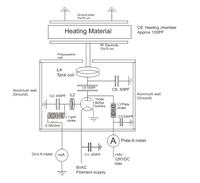
The oscillator is Tuned grid tuned plate (I think) triode used is toshiba 8t25ra rating 25KW

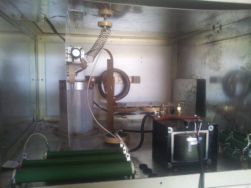
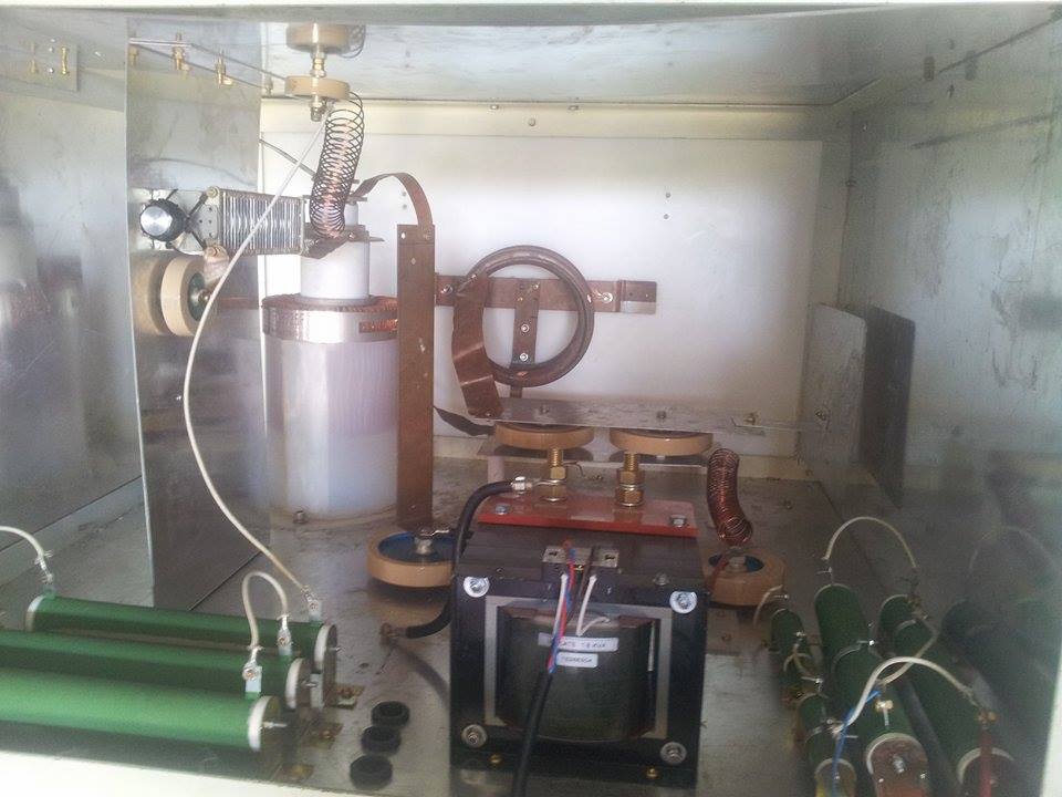
I draw a circuit diagram attached and a picture , anyone help advise how to reduce harmonic?

Thanks , Krit


I don't know what is your test setup, but at those high power levels it's very easy to make intermods in your spectrum analyzer front-end when you look for harmonics.

C5, L4, and C6 forms a PI network which might need adjustment to get lower second harmonic, but keeping high power on fundamental.

The high-power HF amplifiers used in radio-communications use variable capacitors and a variable inductor for those components.
 

Presumed you know how to sort out SA intermodulation, it's absolutely expectable that the power stage generates a considerable amount of harmonics. Harmonic filtering is yet very rudimentary and hardly sufficient to comply with EMC regulations.

Besides tuning of the output circuit, you may need additional LC circuits for a real improvement.
 

Is power of second harmonic raised above the specs? Is working frequency within the specs?
 

I would try to put an inductor in parallel with C5, and greatly increase the value of C5. The resultant circuit would be resonant (i.e. a bandpass) at 27 MHz.

Alternately, you could parallel C5 with a series L-C network tuned to 54 MHz (using high power components and layout, of course).

But I would look at the tube data sheet and make sure that shorting out the 2nd harmonic would not hurt the tube. Otherwise you will need to make a much more complicated non-reflective lowpass filter at the output, possibly using some sort of water cooled load.
 

Status
Not open for further replies.

Part and Inventory Search

Welcome to EDABoard.com

Sponsor

Back
Top