Continue to Site

Welcome to EDAboard.com

Welcome to our site! EDAboard.com is an international Electronics Discussion Forum focused on EDA software, circuits, schematics, books, theory, papers, asic, pld, 8051, DSP, Network, RF, Analog Design, PCB, Service Manuals... and a whole lot more! To participate you need to register. Registration is free. Click here to register now.

[SOLVED] please help me to sort out my SPI comm problem b/w two pic18f452 MCU..details...

Status
Not open for further replies.

Sardar_nayab

Newbie level 4
Joined
Nov 17, 2012
Messages
7
Helped
0
Reputation
0
Reaction score
0
Trophy points
1,281
Activity points
1,326
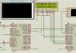
am using master slave concept..

4 pins on both sides (SDI SDO SS SCK)
am using mikro c pro compiler

> i think there is problem of clock that is not generating properly..am using 24MHZ crystal
>no data is received at either end
please help.


master

Code:
sbit Chip_Select           at RE2_bit;
sbit Slave_Select           at RA5_bit;
sbit Chip_Select_Tris           at TRISE2_bit;
sbit led at RB4_bit;

/*
sbit s_din at RB4_bit;
sbit s_dout at RB4_bit;
sbit s_cs at RB4_bit;
sbit s_ss at RB4_bit;
 */

signed short tmp, character, loop, loop2;
int i, size;

char trans[10]=" nayab";
char rec[10];

void main() {
     TRISB = 0x00;
     //TRISC= 0x93;
     Chip_Select_Tris =0;
     trise2_bit=0;
     trisa5_bit=0;


//************$$$$$$$$$$$$$$$$$$$$$$$$$$$$/////////
    TXSTA=0x20;
    RCSTA=0x90;
    SPBRG = 38;
    
    SSPSTAT = 0xC0;
    SSPCON1 = 0x22;

 //************$$$$$$$$$$$$$$$$$$$$$$$$$$$$****************************/////////
   Chip_Select=1;
   Slave_Select =1;
   re2_bit=1 ;
   led=0;

 //************$$$$$$$$$$$$$$$$$$$$$$$$$$$$****************************/////////


    //SPI1_Init();
    SPI1_Init_Advanced(_SPI_MASTER_OSC_DIV64, _SPI_DATA_SAMPLE_MIDDLE, _SPI_CLK_IDLE_LOW, _SPI_LOW_2_HIGH);

   while(1)
   {
   
   led=~led;
   
   Slave_Select =0;


    for(i=0;i<10;i++)
    {
     Delay_ms(10);
     spi1_write(trans[i]);


    }
    Slave_Select =1;


   }


}


slave

Code:
sbit Chip_Select           at RE2_bit;
sbit Chip_Select_Tris           at TRISE2_bit;
sbit SCKK   at TRISC3_bit;
sbit led at RB4_bit;

signed short tmp, character, loop, loop2;
int i, size;


char trans[10]="nayab ";
char rec[10];
char urec[10]="notyet ";
char buffer[10]="attique ";

void main() {
     TRISB = 0x00;
     TRISC= 0x9B;
     trisa5_bit=1;
     Chip_Select_Tris =1;


//************$$$$$$$$$$$$$$$$$$$$$$$$$$$$/////////
    TXSTA=0x20;
    RCSTA=0x90;
    SPBRG = 38;
    
    SSPSTAT = 0x40;
    SSPCON1 = 0x24;

 //************$$$$$$$$$$$$$$$$$$$$$$$$$$$$****************************/////////
   Chip_Select=1;
   led=0;
   PORTC=0;
   ra5_bit=1;
 //************$$$$$$$$$$$$$$$$$$$$$$$$$$$$****************************/////////

    UART1_Init(9600);
    //SPI1_Init();

    SPI1_Init_Advanced(_SPI_SLAVE_SS_ENABLE, _SPI_DATA_SAMPLE_MIDDLE, _SPI_CLK_IDLE_LOW, _SPI_LOW_2_HIGH);

   while(1)
   {
      led=~led;
   
    for(i=0;i<10;i++)
    {
      Delay_ms(10);
      if(Chip_Select==0)
      {
        rec[i]=spi1_read(sspbuf);
        
        led=~led;

      }


    }
   
   for(i=0;i<10;i++)
    {
      led=0;
     uart1_write(rec[i]);
     Delay_ms(10);

    }
     for(i=0;i<10;i++)
    {
    Delay_Ms(10);
      if (UART1_Data_Ready() == 1)
         urec[i] = UART1_Read();
         
          led=~led;


    }

 
 for(i=0;i<10;i++)
    {

     uart1_write(urec[i]);
     Delay_ms(10);

    }
   

  }


}
 
Last edited by a moderator:

Where is the TRISE Initalization for master and Slave? And why are you not using SPI library functions of mikroC? Are you simulating in Proteus? If yes, zip and post the proteus file and project files.
 
Last edited:

hi internetuser2k12 thanks for reply

TRIS for SPI master and slave are right below from where main function starts(TRISC = ox9B)..and am using mikro c pro and these are the library funtions(spi1_read etc).
yes i simulated it in protus working fine the but not on breadbord.. real time i think the problem is SCK..
my project folder contaning master slave code in pro and protious file is attached
 

Attachments

  • pro.rar
    141.7 KB · Views: 82

Check for hardware problems.

- - - Updated - - -

Try to use LAT registers. For PIC18 LAT registers should be used.
For master change

Code:
sbit Chip_Select at RE2_bit;
sbit Slave_Select at RA5_bit;
sbit Chip_Select_Tris at TRISE2_bit;
sbit led at RB4_bit;

to

Code:
sbit Chip_Select at LATE2_bit;
sbit Slave_Select at LATA5_bit;
sbit Chip_Select_Tris at TRISE2_bit;
sbit led at LATB4_bit;

For slave change

Code:
sbit Chip_Select at RE2_bit;
sbit Chip_Select_Tris at TRISE2_bit;
sbit SCKK at TRISC3_bit;
sbit led at RB4_bit;

to

Code:
sbit Chip_Select at LATE2_bit;
sbit Chip_Select_Tris at TRISE2_bit;
sbit SCKK at TRISC3_bit;
sbit led at LATB4_bit;
 

thanks internetuser2k12 ..

my problem area is in serial clock that is not generated by MCU..
can you figure out the possible problem..any configuration etc mistak

- - - Updated - - -

thanks internetuser2k12 ..

my problem area is in serial clock that is not generated by MCU..
can you figure out the possible problem..any configuration etc mistak
 

RA5 and RE2 pins of master and slave has analog inputs. Have you configured them as digital in ADCON1 register?

ADCON1 for master and slave is 0x87.

RCSTA=0x90; in slave is wrong

RCSTA.CREN = 0; receiver is disabled. slave only transmits data to terminal. slave doesn't receive data through serial uart.

What is the purpose of Chip_Select=1; in slave?

There is if(Chip_Select == 0) in slave, when does Chip_Select become 0? Is master making slaves Chip_Select 0 anywhere in masters code?
 
Last edited:

ok..but it has any concern with serial clock..i.e RC3
 

NO. maybe spi is not initialized properly or maybe your pic is faulty.
 

master slave select is connected with slave chip select..in my cct..if master selects the slave it stars readind data by spi1_read()...
and as for usart is concern its not the problem right now

- - - Updated - - -

i have tested both by SPI_init() and directly by putting values in registers...but still pic is not generating sck..

do i need to config rc3(sck ) as digital I/O as well?
 

No you don't have to configure RC3. Are you just simulating in Proteus or are you testing on real hardware? maybe in proteus PIC18F452 is faulty. Check with some other PIC.

Did you select HS oscillator in mikroC ?


Try this code. it is working, Master is transmitting string "Atiqueet" but there is a timing problem. Some letters get skipped.
 

Attachments

  • SPI MS.rar
    93 KB · Views: 91
  • pic spi ms.jpg
    pic spi ms.jpg
    419.8 KB · Views: 98
Last edited:

Yes i am testing it in real time h/w...am using 24mhz crystal module..
and in protiuos serial clock dosnt matter
yes i selected hs ocilator ...and crystal clock is working fine on h/w
 

Status
Not open for further replies.

Similar threads

Part and Inventory Search

Welcome to EDABoard.com

Sponsor

Back
Top