Continue to Site

Welcome to EDAboard.com

Welcome to our site! EDAboard.com is an international Electronics Discussion Forum focused on EDA software, circuits, schematics, books, theory, papers, asic, pld, 8051, DSP, Network, RF, Analog Design, PCB, Service Manuals... and a whole lot more! To participate you need to register. Registration is free. Click here to register now.

Please help me in designing a LED Circuit.

Status
Not open for further replies.

Garetek

Newbie level 5
Joined
Jan 5, 2012
Messages
10
Helped
0
Reputation
0
Reaction score
0
Trophy points
1,281
Activity points
1,368
Good afternoon,
I am attempting to build a LED Circuit that is more complex that I know how to do. It runs off of a 9 volt battery and 3 LED's.
First off the Math
Battery 9 volt
3mm Red/Green LED
Red: 1.9-2.5 Volts @ 20ma
Green: 2.9-3.5 Volts @ 20ma
5mm White/Green LED
White:2.5-3.3 Volts @ 25ma
Green: 2.9-3.5 Volts @ 25ma

(White LED x2+Green3mm LED) 2.9+2.9+2.9=8.7 Running all three LEDS at 2.9 Volts.
(Green LED x2+Red LED)2.9+2.9+2.5=8.3 volts. Running the two green at 2.9

Resistors
(White LED x2+Green3mm LED) 9-8.7= .3 / .020(max milliamp rated for the smaller 3mm light)= 15 omhs
(White LED x2+Green3mm LED) 9-8.7= .3 *.020(max milliamp rated for the smaller 3mm light)= .006 watts
(Green LED x2+Red LED) 9-8.3= .7 / .020(max milliamp rated for the smaller 3mm light)= 35 Omhs
(Green LED x2+Red LED) 9-8.3= .7 * .020(max milliamp rated for the smaller 3mm light)= .014 watts

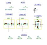
Now the tricky part, how to wire it all together.
Below is a LED Diagram that I made feel free to tell me its wrong, but any help would be greatly appreciated.
LEDComplex.png
5 represents the switch that will hopefully turn off one set of colors and on the other set.(Green&Red-White&Green)
6 represents the main on off switch for the device.
 

What type of switches are you using for?
The two pins bicolor LED (white/green) need to change polarity in order to change colors.
Without using a DPDT switch (Double Pole Double Throw ) you can’t use both colors of this LED.
Switches
 

You are doing the arithmetic based on assumed forward voltages. You can't simply choose them.

You must design for the worst case, i.e. that the diodes will exhibit the maximum quoted voltages.

In your first example, 2 x white plus 1 x 3mm green, the voltages you have to assume are the maximum figures; 3.3 + 3.3 + 3.5.

In the event that the particular examples of l.e.ds coveniently exhibited the forward voltages you would like, the difference between their sum and the battery voltage is so small that they wouldn't stay bright for long, unless of course you use a very large capacity battery so that its terminal votage doesn't drop too rapidly.

If you could use a 12V battery you would not run into the problems to which I refer.
 

Because two of the 3 LEDs have one terminal in common you can put series 3 LEDs to create two different colored banks…
 

What type of switches are you using for?
The two pins bicolor LED (white/green) need to change polarity in order to change colors.
Without using a DPDT switch (Double Pole Double Throw ) you can’t use both colors of this LED.
Switches

Okay, well that takes out the momentary switch, and we will just make room to accept a double post double throw switch, and manually change it when ever events occur.

---------- Post added at 17:09 ---------- Previous post was at 17:07 ----------

You are doing the arithmetic based on assumed forward voltages. You can't simply choose them.

You must design for the worst case, i.e. that the diodes will exhibit the maximum quoted voltages.

In your first example, 2 x white plus 1 x 3mm green, the voltages you have to assume are the maximum figures; 3.3 + 3.3 + 3.5.

In the event that the particular examples of l.e.ds coveniently exhibited the forward voltages you would like, the difference between their sum and the battery voltage is so small that they wouldn't stay bright for long, unless of course you use a very large capacity battery so that its terminal votage doesn't drop too rapidly.

If you could use a 12V battery you would not run into the problems to which I refer.

I am fairly new to building electronics, I had assumed(and made an arse out of myself) that I could pick how much power I wanted to goto the Leds. I can up to a 12volt batt with little modification to the design, and redo the math for the resistors at max power.
 

Is this the correct components list? (except the number of resistors)
 

Attachments

  • Status A.JPG
    Status A.JPG
    33.9 KB · Views: 64

I am fairly new to building electronics, I had assumed(and made an arse out of myself) ...

Not at all, it's part of the learning curve.

I can up to a 12volt batt with little modification to the design, and redo the math for the resistors at max power.

Yes, just do the arithmetic using the maximum figures for forward voltages, and 12V will be fine.
 

Is this the correct components list? (except the number of resistors)

Yes. I could post links to everything if that would help?

---------- Post added at 18:26 ---------- Previous post was at 18:10 ----------

Yes. I could post links to everything if that would help?

**broken link removed**

Standard 23a 12volt Battery

Resistors, have not done the math for, but they will be bought at Radio shack, as well as a DPDT Switch.
 

I see now there’snt any ''two pins bicolors LEDs'', you are using only ''3 pins LEDs''.
Try using a SPDT switch (Single Pole Double Throw) and LEDs connected in parallel. (each LED may use a series resistor = 470 ohms – 680 ohms )
:-D Some examples to connect 3 LEDs:
 

Attachments

  • bicolor LEDs 1.GIF
    bicolor LEDs 1.GIF
    25.9 KB · Views: 61
  • bicolor LEDs 2.GIF
    bicolor LEDs 2.GIF
    26 KB · Views: 60
  • bicolor LEDs 3.GIF
    bicolor LEDs 3.GIF
    26.1 KB · Views: 58

I see now there’snt any ''two pins bicolors LEDs'', you are using only ''3 pins LEDs''.
Try using a SPDT switch (Single Pole Double Throw) and LEDs connected in parallel. (each LED may use a series resistor = 470 ohms – 680 ohms )
:-D Some examples to connect 3 LEDs:

So, now that I can see the the images I see what you are getting at. However, I'm just making sure that the resistors are placed right. They are on the negative side of the LEDs. Or Common pole to negative terminal of the battery?
 
Last edited:

I see it does not matter where the resistors are placed, as long as they are in the circuit. So now I just need to do the math to figure out how much they need to resist. Since I mam going to want to have white/white/green up. Can I assume that I can use the full power of the two whites, and tie them into one resistor. The 3mm green would be stand alone. Then the Green/Green/Red with the two greens tied together and the Red stand alone. If i am correct, then all I have to do is finish my math and out the door to radio shack I go.

---------- Post added at 10:33 ---------- Previous post was at 10:09 ----------

So I redid the math, and came up with the following.
Resistor 1 216 @ .135 Two White LEDS
Resistor 2 200 @ .125 Two Green LEDS
Resistor 3 475 @ .19 One RED LED
Resistor 4 425 @ .17 One Green LED

If I did it correctly.
 

Let us suppose we have 9V.
Two white LEDs in series would need about 6.6V @20mA so the resistor value could be (9V-6.6V) / 20mA = 120R (nice value!)
The same applies for the two green LEDs and their series resistor could be 120R.
For one green LED, (9-3.3)/20 = 285R (that is 270R or 330R)
For one red LED, (9-2)/20 = 350R (that is 330R or 390R)
Obviously, the last two configurations suffer of relatively high power loss since only one LED is driven by 9V.

Right, but I upped it to a 12v because the battery is much smaller and I need all the room I can get.
 

I think you know that if you have 12V you can light 3 white (or green) LEDs connected in series. In this case, the resistor value would equal to:
(12 - 3*3.3) / 20mA = 105R (that is 100R or 120R) you can even use higher value to save power.

Also on 12V one can light 5 red LEDs (in series) with the same current:
(12 - 2*5) / 20mA = 100R , or any higher value to save power.

Note: If you use less number of LEDs in a branch, the power of the removed LED will have to be dissipated (lost) by the limiting resistor (in this case, its value will be higher than the ones calculated above)

Note: It is possible mixing different color LEDs as long the total of their forward voltages is less than 12V (actually less than 11V, the small difference is for the limiting resistor).
 
Last edited:

I think you know that if you have 12V you can light 3 white (or green LEDs) connected in series. In this case, the resistor value would equal to:
(12 - 3*3.3) / 20mA = 105R (that is 100R or 120R) you can even use higher value to save power.

Also on 12V one can light 5 red LEDs (in series) with the same current:
(12 - 2*5) / 20mA = 100R , or any higher value to save power.

Note: if you use less number of LEDs in a branch, the power of the removed LED will have to be dissipated (lost) by the limiting resistor (in this case, its value will be higher than the ones calculated above)
I'm shooting for only having 3 LEDs lite up, or when th switch is thrown it switches to a different three.
Cool. So bigger saves Power. And I am safe in using 1/4 or .25 watt resistors.
 

To calculate the power of the limiting resistor (Rs) you can measure its voltage, say Vs:
Ps = Vs * Vs / Rs
Vs = 12 - sum of LED's voltages

Approximately:
If Rs = 100 and the current is 20mA, we can use:
Ps = Is * Is * Rs = 0.020 * 0.020 * 100 = 0.04 W
That is 40mW only
 

Status
Not open for further replies.

Part and Inventory Search

Welcome to EDABoard.com

Sponsor

Back
Top