Continue to Site

Welcome to EDAboard.com

Welcome to our site! EDAboard.com is an international Electronics Discussion Forum focused on EDA software, circuits, schematics, books, theory, papers, asic, pld, 8051, DSP, Network, RF, Analog Design, PCB, Service Manuals... and a whole lot more! To participate you need to register. Registration is free. Click here to register now.

Please help finding resistance !

Status
Not open for further replies.

ArFa

Junior Member level 2
Joined
Dec 27, 2010
Messages
23
Helped
0
Reputation
0
Reaction score
0
Trophy points
1,281
Activity points
1,438
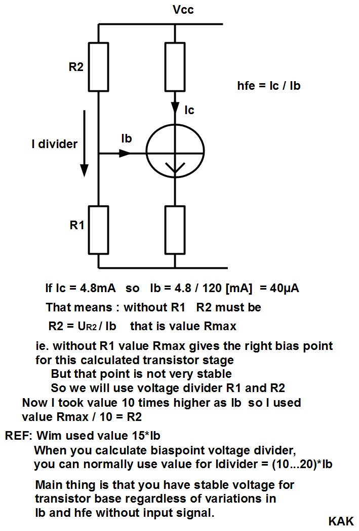
Please can you tell me how to find these parameters: R1=? ; R2=? ; Re=?
if Vcc=18V; Rc=2k(ohm) ; IcQ=4.8 [mA] ; VceQ=6 [V] and beta = 120.

the circuit is:
Code:
http://img18.imageshack.us/i/electrocircuit.png/
**broken link removed**
 

Hello,

Vcc = V(rc) + Vce + Vre. Vce = 6V (from your graph),
V(rc) = 4.8mA*2kOhm = 9.6V,

so Vre must be 18-9.6-6 = 2.4V. Vbe should be around 3.0V (diode voltage drop of 0.6V added).

As hfe = 120, Ire = 2.4/(1.012*4.8mA) = 494 Ohms. (Ie = Ib + Ic)

As a rull of thumb, current through R1-R2 divider is taken about 10...20*Ibase When we use current through R1 = 15*Ib:

Ib = 4.8m/120 = 40uA, so I(R1) = 15*40uA = 600uA. R1 = 3V/600uA = 5 kOhms.

Kind regards,

Wim
 
  • Like
Reactions: ArFa

    ArFa

    Points: 2
    Helpful Answer Positive Rating
Hello,

Vcc = V(rc) + Vce + Vre. Vce = 6V (from your graph),
V(rc) = 4.8mA*2kOhm = 9.6V,

so Vre must be 18-9.6-6 = 2.4V. Vbe should be around 3.0V (diode voltage drop of 0.6V added).

As hfe = 120, Ire = 2.4/(1.012*4.8mA) = 494 Ohms. (Ie = Ib + Ic)

As a rull of thumb, current through R1-R2 divider is taken about 10...20*Ibase When we use current through R1 = 15*Ib:

Ib = 4.8m/120 = 40uA, so I(R1) = 15*40uA = 600uA. R1 = 3V/600uA = 5 kOhms.

Kind regards,

Wim
Please can you explain why is so?

Another calculation....................

Tra_stage_01.pdf

KAK

Please why R2max. ? What is it? And why R2=R2max/10 ?


Thank you very much for replays ...
 

Please why R2max. ? What is it? And why R2=R2max/10 ?

Explanation.........................


Regards KAK
 
  • Like
Reactions: ArFa

    ArFa

    Points: 2
    Helpful Answer Positive Rating
Thank you very much
 

Hello,

There is large spread in hfe, for non-grouped transistors it may vary between 100 and 300, or 10 and 30 for a large power high voltage transistor.

In addition to this, hfe is also strongly dependent on temperature. Best is to look into somee datasheets of bipolar transistors. The may specify nominal hfe versus temperature graph.

In your case, taking a certain non-selected transistor and over, for example, -20 to 80 degr C), actual hfe may be between 50 and 400. So your actual base current can be anything between 4.8mA/400 = 0.012mA and 4.8m/50=0.1mA.

Your R1-R2 voltage divider has internal resistance (R1 parallel to R2) and a certain EMF (Vcc*R1(R1+R2) ). With R1= 5 kOhm and R2 = 23.4 kOhm, internal resistance = 4.1 kOhm and EMF = 3.17V.


The base current introduces a voltage drop over the internal resistance of the voltage divider (so actual base voltage is less then the EMF). Imagine when you have a transistor with low hfe and you are using the circuit at very low temperature, actual base current would be 4.8mA/50 = 0.1mA. This would cause a voltage drop of 0.1m*4.1k=0.39 V. So the actual base voltage would be 3.17-0.39 = 2.77V. Now you may see that the emitter voltage will be less also and your collector current will be less then 4.8mA.

In case of a transistor with large hfe (for example 400), the voltage drop across the internal resistance of the bias resistors would be 4.1k*0.012mA = 0.05V (so base voltage would be 4.17-0.05 = 3.1V, now the collector current may be somewhat above 4.8mA.

So to reduce the bias variation due to spread in hfe, there are practical upper limits on the resistance values you can use for the base bias resistors. You may know that you can reduce the spread in hfe by using grouped transistors (for example BC847 A, B or C).

The 10...20Ib is a rule of thumb. If you really want to see the effect. Do the calculation for the voltage divider for both 10Ib and 20Ib and calculate the actual emitter voltage for varying hfe.

Other issue: R1 and R2 are in parallel with the input of the base, so they reduce the input impedance. If you don't want this, you can use so-called "bootstrapping".

Kind regards,

Wim
 

Status
Not open for further replies.

Similar threads

Part and Inventory Search

Welcome to EDABoard.com

Sponsor

Back
Top