Continue to Site

Welcome to EDAboard.com

Welcome to our site! EDAboard.com is an international Electronics Discussion Forum focused on EDA software, circuits, schematics, books, theory, papers, asic, pld, 8051, DSP, Network, RF, Analog Design, PCB, Service Manuals... and a whole lot more! To participate you need to register. Registration is free. Click here to register now.

piezo buzzer connection

Status
Not open for further replies.

jo12345

Newbie level 4
Joined
Oct 20, 2011
Messages
7
Helped
0
Reputation
0
Reaction score
0
Trophy points
1,281
Activity points
1,316
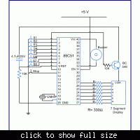
how do i connect the piezo buzzer in my circuit? i hav attached the circuit diagram. its a quiz buzzer.this is a circuit i am mounting on a pcb. the seven segment display works properly and gives me the output. the problem with the circuit is that the piezo buzzer does not work in the circuit though it is in a working condition. one terminal of the piezo buzzer is connected to the pin 32 of AT89C51 and the other to +5V. do i need to connect any capacitor?
please do reply...
thank you
 

The program will reveal details.
 

program

Code:
#include<reg51.h>
unsigned int digi_val[10]={0x40,0xF9,0x24,0x30,0x19,0x12,0x02,0xF8,0x00,0x10};        // Hex value corresponding to the digits 0 to 9
sbit output_on_pin = P3^0;        // Enable pin to enable the seven segment.
sbit stop_pin = P3^1;        // Stop pin to reset the buzzer.
sbit buzzer_pin=P0^0;        //  Buzzer pin to sound the buzzer.
int flag;	

void delay()        // Time delay function
{
    int i,j;
    for(i=0;i<200;i++)
    for(j=0;j<1275;j++);
}

void display(unsigned int current_dig)        // Function to display the resultant digit on the seven segment and sound the buzzer.
{
    P2=digi_val[current_dig];
    output_on_pin = 1;
    buzzer_pin=0;
    delay();
    buzzer_pin=1;
    while(stop_pin != 0);
}  

void buzzer() //Function to monitor the input switches
{
    flag = 0;
    while(1)
    {
        while (P1 == 0xFF);
        
        while (P1 == 0xFE)        //Check if switch 1 is pressed
        {
            flag = 1;
            display(1);
        }

        while (P1 == 0xFD)        //Check if switch 2 is pressed
        {
            flag = 2;
            display(2);
        }    

        while (P1 == 0xFB )        //Check if switch 3 is pressed
        {
            flag = 3;
            display(3);
        }

        while (P1 == 0xF7 )        //Check if switch 4 is pressed
        {
            flag = 4;
            display(4);
        }

        while (P1 == 0xEF )        //Check if switch 5 is pressed
        {
            flag = 5;
            display(5);
        }

        while (P1 == 0xDF)        //Check if switch 6 is pressed
        {
            flag = 6;
            display(6);
        }

        while (P1 == 0xBF )        //Check if switch 7 is pressed
        {
            flag = 7;
            display(7);
        }

        while (P1 == 0x7F )        //Check if switch 8 is pressed
        {
            flag = 8;
            display(8);
        }
      
        P1 = 0xFF;
        stop_pin = 1;
        output_on_pin = 0;
    }
}

void main()
{
    output_on_pin=0;
    stop_pin = 1;
    P1 = 0xFF;
    buzzer();

}
 
Last edited by a moderator:

The peizo works hooking it up straight to the 5v supply? Maybe you need a transistor in there to suplement some of the current if the micro can't source/sink it by itself?
 

please reply.... its urgent
 

Well I would check and make sure the piezo itself is working. The one I have is rated for 5v so simply connect the positive side to 5v and the negative to ground. It should produce a sound. If that works than there is probably something wrong with your program or original wiring.
 

i had already checked the buzzer. it was working perfectly fine. i am unable to understand the problem with the circuit
 

Status
Not open for further replies.

Similar threads

Part and Inventory Search

Welcome to EDABoard.com

Sponsor

Back
Top