Continue to Site

Welcome to EDAboard.com

Welcome to our site! EDAboard.com is an international Electronics Discussion Forum focused on EDA software, circuits, schematics, books, theory, papers, asic, pld, 8051, DSP, Network, RF, Analog Design, PCB, Service Manuals... and a whole lot more! To participate you need to register. Registration is free. Click here to register now.

Pierce tube oscillator not working

Status
Not open for further replies.

neazoi

Advanced Member level 6
Joined
Jan 5, 2008
Messages
4,122
Helped
13
Reputation
26
Reaction score
15
Trophy points
1,318
Location
Greece
Activity points
36,951
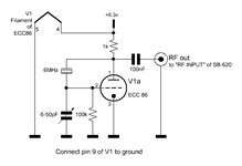
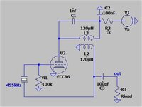
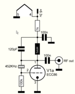
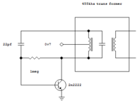
Here http://qrp.gr/tubeosc/ is a pierce low voltage tube crystal oscillator I have designed and it works fine on 6MHz but it does not work with a 452KHz crystal. I tried to remove the variable capacitor but still it does not oscillate. There are no other "resonant" elements to tweak. Any ideas?
 

Attachments

  • tubeosc.jpg
    tubeosc.jpg
    23.6 KB · Views: 141

6.3V Anode Voltage is too low for ECC86. How it worked @ 6MHz ?? Are you sure ? What was the Anode current ?
It also depends on crystal specifications. There are variants for 455 kHz crystals and each one has a target application. There is no rule that every 455 kHz crystal will work, definitely no.
 

    neazoi

    Points: 2
    Helpful Answer Positive Rating
6.3V Anode Voltage is too low for ECC86. How it worked @ 6MHz ?? Are you sure ? What was the Anode current ?
It also depends on crystal specifications. There are variants for 455 kHz crystals and each one has a target application. There is no rule that every 455 kHz crystal will work, definitely no.
Ecc86 is a low anode voltage designed tube. There are lots of radio circuits that use it. There are more tube types of this type too, it is not just the ecc86.
Yes it worked great at 6MHz that I have tried. It even was able to be loaded to 50ohm on the anode output, without stopping oscillation. I did not measure the anode current.
The capacitor is there to shunt some feedback to the ground I think and the result is that by setting it just to the point of "sure start", veeery low sine distortion is achieved.

I also suspected the crystal, so I tried with a ceramic resonator in place and again no oscillation.
 
Last edited:

try 100k => 1Meg

and 1k => 4k7
I have tried a 100k trimmer at the anode and a 1meg trimmer at the grid and varied them but I could not get it to oscillate. I have also tried a 10millihenry choke at the anode (100R self resistance) and no luck...
 

In Pierce configuration, is hard to make the circuit oscillate for crystals below 1MHz. Perhaps you are using a ceramic resonator, not a real crystal which is hard to get for frequencies below 1MHz.
The circuit attach, its a bit more complicate, but oscillates in any conditions, with any type of resonator.
Check the right polarity of L2.

Another option in your Pierce configuration, is to add a series 1mH inductor at the anode (series with the 1k resistor) and place a 122pF cap in parallel with the inductor (will be a resonant circuit on 455kHz). Needs a 100nF decoupling cap to ground at the connection of the 1mH inductor and the 1k resistor. Simulation shows that the circuit oscillates.
 

Attachments

  • 455kHz_LO.jpg
    455kHz_LO.jpg
    22 KB · Views: 99

    neazoi

    Points: 2
    Helpful Answer Positive Rating
In Pierce configuration, is hard to make the circuit oscillate for crystals below 1MHz. Perhaps you are using a ceramic resonator, not a real crystal which is hard to get for frequencies below 1MHz.
The circuit attach, its a bit more complicate, but oscillates in any conditions, with any type of resonator.
Check the right polarity of L2.

Another option in your Pierce configuration, is to add a series 1mH inductor at the anode (series with the 1k resistor) and place a 122pF cap in parallel with the inductor (will be a resonant circuit on 455kHz). Needs a 100nF decoupling cap to ground at the connection of the 1mH inductor and the 1k resistor. Simulation shows that the circuit oscillates.
What is your anode voltage in your simulation?
What topology is it?
 

ECC86 was designed for car radios. At that time, most of the cars use 6V batteries. The tube works with anode voltages between 6V and 25V.
The slope of the tube is not very high, only 2.6mA/V at 6V, compared to a 100V tube as ECC88 which has about 12mA/V. This make a challange the tube to oscillate without proper feedback.
Both approaches that I mentioned above, improves the feedback, but needs some experiments to make it work.
 

    neazoi

    Points: 2
    Helpful Answer Positive Rating
ECC86 was designed for car radios. At that time, most of the cars use 6V batteries. The tube works with anode voltages between 6V and 25V.
The slope of the tube is not very high, only 2.6mA/V at 6V, compared to a 100V tube as ECC88 which has about 12mA/V. This make a challange the tube to oscillate without proper feedback.
Both approaches that I mentioned above, improves the feedback, but needs some experiments to make it work.
What is the anode voltage in your simulation?
 

Obviously, the different parameters of 450 kHz versus 6 MHz crystal are responsible for different behaviour. We would need a detailed electrical specification of the crystal to calculate oscillation condition. If the infomation doesn't exist, we can't go beyond comparision with similar circuits and suggestions for empirical trial.
--- Updated ---

What is the anode voltage in your simulation?
In addition, what are the crystal model parameters?
 

+6.3V
 

    neazoi

    Points: 2
    Helpful Answer Positive Rating
I tried this circuit at first and it did not work. I tried a 1meg trimmer at the grid, changing it's value to see if it will oscillate. I connected a 100pF fixed and a 5-50pf variable in parallel to the inductor, to bring it at exact resonance. I also tried to short the 1K. nothing...
 

Attachments

  • Capture.PNG
    Capture.PNG
    14.5 KB · Views: 80

I think you are simply seeing lack of gain. The 452KHz crystal (which should be its series resonant frequency, the 6MHz one was probably its parallel resonant frequency) will need more drive signal. Adding the tuned circuit would certainly help by increasing the impedance at the anode but still no guarantee there would be enough. Just a thought - try swapping the tube with a JFET, it might work better.

Brian.
 

    neazoi

    Points: 2
    Helpful Answer Positive Rating
I think you are simply seeing lack of gain. The 452KHz crystal (which should be its series resonant frequency, the 6MHz one was probably its parallel resonant frequency) will need more drive signal. Adding the tuned circuit would certainly help by increasing the impedance at the anode but still no guarantee there would be enough. Just a thought - try swapping the tube with a JFET, it might work better.

Brian.
I was hoping to get this running with a tube, so as to match an old wooden radio and be used as a BFO for it. Now the wooden radio has already a HV, but It would be easier and cheaper to do it using just the heaters (rectified).
As I am trying to get the circuit running on low +B, more and more components are added, and still no success. Also, heaters rectification would probably interfere with the existing circuit operating on AC. There are so many problems and the final thing does not worth it at the end.

I wonder... if I connect the two triodes of the ECC86 in parallel, will I be avle to get more gain? Or even better in series, the second triode to be an RF amplifier and then take the feedback from it's output?

Another option could be to find an LC oscillator and use it with a 455KHZ IF transformer as a resonator. This might (or might not) make it easier to oscillate and also adjustable exactly. Stability would not be that good but it might be adequate for these low frequencies. IF you have anything in mind please let me know. Obviously I refer to low +B tube circuits.
The simplest tested tranzistorized BFO is probably this one from my website. http://qrp.gr/bfo/
 

Attachments

  • bfo.PNG
    bfo.PNG
    5.8 KB · Views: 77
Last edited:

In your tube Pierce oscillator #14 you forgot to place a capacitor from Grid to ground. Simulation shows that a 100pF capacitor would be fine.
As I said, the slope of ECC86 is small, and if the tube is old with many working hours, could be even smaller.
If still not oscillating, the circuit posted in #6 will work for sure.
 

    neazoi

    Points: 2
    Helpful Answer Positive Rating
In your tube Pierce oscillator #14 you forgot to place a capacitor from Grid to ground. Simulation shows that a 100pF capacitor would be fine.
As I said, the slope of ECC86 is small, and if the tube is old with many working hours, could be even smaller.
If still not oscillating, the circuit posted in #6 will work for sure.
I have connected a 470pF there as an experiment which did not work. I will reduce this and let you know.
You seem confident for the other circuit in #6 so I will try this as a last resort.

MEanwhile, what is your oppinion about a franklin oscillator which uses 2 devices (the other triode section of the ecc86) and has more gain?
A HV example of the topology is shown here https://worldradiohistory.com/hd2/I...-UK-IDX/IDX/50s/SWM-1956-12-OCR-Page-0012.pdf
 

Attachments

  • Capture.JPG
    Capture.JPG
    37.5 KB · Views: 95

More gain, no pain...this characterize the tubes era...
I am not a big fan of Franklin oscillators, mainly because in Franklin oscillators without resonant circuits at the output, is almost impossible to get a sinusoidal signal. As a Colpitts can easily get, for example..
Even if they state good stability, when you introduce another active component in the circuit, all the problems that an oscillator have, doubles also.
 

    neazoi

    Points: 2
    Helpful Answer Positive Rating
Status
Not open for further replies.

Part and Inventory Search

Welcome to EDABoard.com

Sponsor

Back
Top