Continue to Site

Welcome to EDAboard.com

Welcome to our site! EDAboard.com is an international Electronics Discussion Forum focused on EDA software, circuits, schematics, books, theory, papers, asic, pld, 8051, DSP, Network, RF, Analog Design, PCB, Service Manuals... and a whole lot more! To participate you need to register. Registration is free. Click here to register now.

[General] PICPgm lvisp programmer recognized as Tait

Status
Not open for further replies.

stachuc

Newbie level 4
Newbie level 4
Joined
Nov 30, 2013
Messages
6
Helped
0
Reputation
0
Reaction score
0
Trophy points
1
Visit site
Activity points
50
Hi All

Just started my adventure with micro-controllers.

I have build a LVISP programmer as described here: http://picpgm.picprojects.net/hardware.html#LVP_PROGRAMMER
but when I autodetect in PICPgm it says it is a Tait Classic PIC Programmer.
And the PIC device is not detected.

I enabled test and checked MCLR, PGM, CLOCK and DATA and their voltage do change when I toggle them on the screen.

Any idea what to do to have PICPgm report the programmer correctly and why PIC 18F2480 or 18F2550 can not be recognized?
 

I don't know why but it just started to recognize it correctly, except PIC, but at least the programmer is now recognized by PICPgm just fine.

I did play with the "Pin Configuration" in Hardware/Hardware Selection/Configuration...
First MCLR, Clock and Data Out were marked as "Invert" i have removed it and it seams to help.

I can choose my PIC manually and it seams as it is working but it is still marked as "unknown PIC"
 

Hi,

Welcome to the forum.

The lvpisp programmer is about as basic as you can get and it may work though have never tried one.

The Tait programmer further down the page is the design I originally used though it was a bit hit and miss at times.

While any of those designs might work for you ( some are depandant on your pc ports being compatible) I would stongly suggest you get or make a Pickit programmer.

You can buy them new as a genuine Microchip Pickit2 or Pickt3 or if make a simpler version of the Pickit2 from the many diy plans you will find if you search this forum, some include a basic programmer to allow you to program the pic18f2550 chip needed for the Pickit2.

Though building you own might seem a good thing, I would say you are much better buying a genuine Pickit programmer ( which will only cost just a bit more than a diy one) so you have a fully working programmer and debugger that will allow you to get going with your programming and circuit design without constantly battling with a often wonky diy programmer
 

Thanks wp100,
You probably right, but the thing is I want to understand how it work, from the beginning. Maybe that stupid but ...

Anyway,
there is some progress with my programmer. So I confirm that as long as the circuit is correct the PICPgm will recognize the programmer. But the programmer needs to be selected manually. To get the PIC recognized, this one works in auto, I had to have all PIN CONFIGURATION unmarked accept for PGM/Vdd, this one had to be "invert".

Now the programmer and PIC is recognized but there are some problems with Config Bits ...
 

Hi,

It is good practice to set your Config bits in your program code, would expect / think that program should pick them up from your program code automatically ...?
 

Thanks for posting.
Can you recommend any manual about those configuration bits? Looks like for each PIC and each compiler the way of defining them is different.
I'm trying to do it with MPLAB IDE it looks like in the program it should start with "__config" but what comes after it is confusing ...
 

Hi,


Someone in this forum recently posted a link to a good article on the config bits, but afraid I have lost that bookmark.

If you search here and the web on 'pic micro configuation bits' you will find various articles, this link is a good tutorial for assembly and C.
**broken link removed**

Its much better if you clearly show your config bits in your code like CONFIG OSC=XT .

In MPlab if you goto the Configure Menu, Config Bits you can manually select show the bit options available for the chip you specify, though that will only pass them to the programmer as a number like 0x3F9E.
( note the little box for including them in your code or not)
 

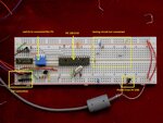
This is how my programmer looks like at the moment. PICPgm recognize the programmer in auto-mode and PIC chip as well, no problems

DSCN0382 (Large).JPG

After pressing "Program PIC" I got a message "programming successful" and PIC can be verified without any problems. But not sure if the PIC is doing what expected I need some practice in programming ...
 

Hi,

Still going at it ? thought you had sorted it ...

If you get programing Successful that sounds good, however to be doubly sure, after programming power it all off, then reload your code into the programmer and just press Verify to see if your code is still the same as whats in the chip.

Your breadboard looks ok, with the power lines and pin 1 connected to +5v.
Some times the breadboard connections can be problematic, partic on the crystal connections which are very thin leads and do not always make sound contact for there very high speed small signals.
Two ways around that, solder the caps and crystal together with 3 thicker connection wires to plug into the breadboard.
The easier way is to just use the internal oscillator which is fine for most diy projects execept for running the chips USB functions etc.

Post your program code so we can see it you have any faults there...
 

Hi,

Below is a led flasher .hex code to test your board with, it runs fine on my 2550 chip.

PortA are inputs, B and C are all outputs and it uses it own internal oscillator to flash all of PortB at 1 second intervals, so no need to worry about your crystal connections.
You can use a led on the output/s via a 330r resistor or simply measure the pins with a voltmeter to prove your chip works.

The Config parameters are built in to the code, but if you have to manually enter them on your programmer these are essential changes/basics, though these are in Assembler layout.
CONFIG FOSC=INTOSCIO_EC, WDT=OFF, PWRT=ON, BOR=OFF, MCLRE=OFF, LPT1OSC=OFF, XINST=OFF
CONFIG LVP=OFF, VREGEN=OFF, PBADEN=OFF, DEBUG=OFF

Important mod you need to do on your board, any chip you use should alway have a 100nf capacitor across its + and - pins .
Particularly important on the Pic and place it as close to the chips pins as possible.
 

Attachments

  • billyboy.zip
    321 bytes · Views: 65

Thanks wp,
Now I'm traveling and will be back home after Christmas, then I will continue. I was trying to investigate a little bit those config parameters but was not able to find much, not much time for it as well.

But what I can see right now is that you have LVP=OFF and that will not work with lvisp programmer as it is a low voltage, for this programmer it needs to be LVP=ON, if I'm correct ...

Hi,

Sorry, missed that point, here it is again with LVP=ON

Also in the Zip is the 2550.INC file which shows the default registers and CONFIG bits for that chip and Microchips Config tutorial ( basic parameters written in 2001)

Assuming you have MPLAB loaded, with a project open, look in the Configure dropdown menu which shows the Config options for the chip specified in the code.

hth
 

Attachments

  • billyboy.zip
    208.4 KB · Views: 59

Status
Not open for further replies.

Part and Inventory Search

Welcome to EDABoard.com

Sponsor

Back
Top