Victor Crisostomo
Newbie level 2
Hello all! first post wee. just want to ask for help. im having *some* problem with the pickit clone i made and am stuck
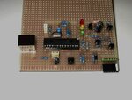
made this DIY pickit clone from the blueroom pickit2 lite schematic. it works fine, but apparently it only has programmer capabilities and not debugging ones. i wanted to debug and i get the "Unable to enter debug mode" error.
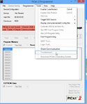
when i tried to debug/run/animate the code it just gives PKError0024 (unable to establish a valid vdd on the target -attempted 5 read 0), so i thought it must be related to the vdd pin, and the removed components as well. the lite schematic connects the +5v to the 1n5817 schottky connected to vdd, so it must be reasonable that always the "target power is detected".
then i found a schematic of the Junebug's pickit2 programmer/debugger (https://www.robotshop.com/media/files/pdf/junebug-assembly-instructions.pdf). it had the same schematic but added the push-pull MOSFET pair connected to the VDD_TGT_N and VDD_TGT_P pins, and so i removed the direct +5 to schottky connection and added the mosfet switch circuits.
unfortunately the programmer still cannot run in debug mode and gets the same pkerror0024 error. also, it still "detects" target power even when the pickit2 is NOT connected to any target.
also a related issue probably, that in the pk2 lite, the target circuit wont run unless the usb is removed then reconnected. and when the pickit is connected to MPLAB/pickit2 app the circuit stops. the error went worse when the mosfets were installed. at first nothing new happened (connect-reconnect-connect to mplab) then when i corrected the pin connection on the n-mosfet (turned it around coz of apparent inverted pinout), it stopped running the circuit. and since "target power detected" there is no way to switch it on. help please
also tried:
1. disconnecting VDD_FB from the VDD pin. magically the pin still measures some 4.x volts on the voltmeter and it is deteced as target power
2. disconnecting the switch/mosfets (except the connections to GND). didnt work
sooo
1. what is wrong with what i am doing and how could i enable debug mode?
2. are (a) the pullup/pulldown on pins 24 and 25 critical? also, is the op-amp VDD_ADJ circuit in anyway essential to entering debug mode?
thats all good morning/night thanks guys
p.s. mods to the circuit: used 1n5819 for both schottky diodes on the schematic, also minor difference in resistor/capacitor values. dont think theyre part of the problem (yet)
made this DIY pickit clone from the blueroom pickit2 lite schematic. it works fine, but apparently it only has programmer capabilities and not debugging ones. i wanted to debug and i get the "Unable to enter debug mode" error.
when i tried to debug/run/animate the code it just gives PKError0024 (unable to establish a valid vdd on the target -attempted 5 read 0), so i thought it must be related to the vdd pin, and the removed components as well. the lite schematic connects the +5v to the 1n5817 schottky connected to vdd, so it must be reasonable that always the "target power is detected".
then i found a schematic of the Junebug's pickit2 programmer/debugger (https://www.robotshop.com/media/files/pdf/junebug-assembly-instructions.pdf). it had the same schematic but added the push-pull MOSFET pair connected to the VDD_TGT_N and VDD_TGT_P pins, and so i removed the direct +5 to schottky connection and added the mosfet switch circuits.
unfortunately the programmer still cannot run in debug mode and gets the same pkerror0024 error. also, it still "detects" target power even when the pickit2 is NOT connected to any target.
also a related issue probably, that in the pk2 lite, the target circuit wont run unless the usb is removed then reconnected. and when the pickit is connected to MPLAB/pickit2 app the circuit stops. the error went worse when the mosfets were installed. at first nothing new happened (connect-reconnect-connect to mplab) then when i corrected the pin connection on the n-mosfet (turned it around coz of apparent inverted pinout), it stopped running the circuit. and since "target power detected" there is no way to switch it on. help please
also tried:
1. disconnecting VDD_FB from the VDD pin. magically the pin still measures some 4.x volts on the voltmeter and it is deteced as target power
2. disconnecting the switch/mosfets (except the connections to GND). didnt work
sooo
1. what is wrong with what i am doing and how could i enable debug mode?
2. are (a) the pullup/pulldown on pins 24 and 25 critical? also, is the op-amp VDD_ADJ circuit in anyway essential to entering debug mode?
thats all good morning/night thanks guys
p.s. mods to the circuit: used 1n5819 for both schottky diodes on the schematic, also minor difference in resistor/capacitor values. dont think theyre part of the problem (yet)