Continue to Site

Welcome to EDAboard.com

Welcome to our site! EDAboard.com is an international Electronics Discussion Forum focused on EDA software, circuits, schematics, books, theory, papers, asic, pld, 8051, DSP, Network, RF, Analog Design, PCB, Service Manuals... and a whole lot more! To participate you need to register. Registration is free. Click here to register now.

PIC32MX250F128D UART rx and tx problem

Status
Not open for further replies.

rajib.das

Member level 3
Joined
Oct 23, 2013
Messages
54
Helped
0
Reputation
0
Reaction score
0
Trophy points
6
Activity points
415
Hi all

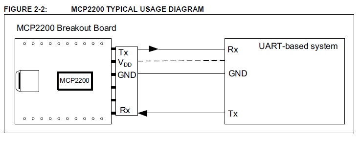
I am currently working on UART coms with PIC32MX250F128D. I am also using the MCP2200 for serial coms between PC USB and PIC UART. Please see the attachments for Data Sheet.


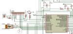
You can see in the schematic , I am Using MC_Pin37(RC4) as Rx1 and MC_Pin38(RC5) Tx1 while I am using the UART_1 channel. I am also using MikroC pro for PIC32. My Project settings are
Project Settings.gif

Used MikroC Code:
Code:
void Initiate_UART(void){
      //   Unlock_IOLOCK();
      pps_result1 = PPS_Mapping(_RPC4, _INPUT, _U1RX); 
      pps_result2 = PPS_Mapping(_RPC5, _OUTPUT, _U1TX); 
      //   Lock_IOLOCK();

      UART1_Init(56000);                 // Initialize UART module at 56000 bps
      Delay_ms(10);                     // Wait for UART module to stabilize

}

//--------------------------------------in Main---------------------------------------------
void main() {
   Initiate_ADC();
   Initiate_LCD();

   Initiate_UART();
   uart_rd = 0;
//--------------------------in While loop------------------------------------------------


While(1){
         
         uart_rd = UART1_Read();     // read the received data
         Delay_ms(10);
         IntToStr (uart_rd, display_Str);
         Lcd_Cmd(_LCD_CLEAR);               // Clear displayite text in first row
         Lcd_Cmd(_LCD_CURSOR_OFF);          // Cursor off/ Write text in second row
         Lcd_Out(1,1,"UART TEST:     ");                 // Write text in first row
         Lcd_Out(2,1,display_Str);                 // Write text in second row
         Delay_ms(1000);

         if(uart_rd = 0) UART1_Write(10);
         else UART1_Write(uart_rd);
}
}

RESULT:
uart_rd is always Zero. that's mean UART_Rx is reading nothing.
and sending 250 instead of 10.(USART Terminal Having Baud Rate 9600).

I have tried lot of ideas and still remain clueless.

Please if anybody can share their experiences or few ideas will much appreciated.

Thanks
 

Attachments

  • MCP2200 Breakout Module User Guide.pdf
    268.1 KB · Views: 74
  • PIC32MX250F128D.pdf
    5.9 MB · Views: 67
  • UART.jpg
    UART.jpg
    143.7 KB · Views: 81
Last edited by a moderator:

That device certainly does have USB OTG capability but that is not how it is used according to the circuit diagram you have provided. (I can't see the first diagram you have provided - it does not 'click to enlarge'.) You cannot connect the UART directly to the USB connector. I can only assume you are somehow just using the connector to wire up to a serial port on the terminal.
I have not used that MCU but reading the data sheet I don't think the PPS settings are correct. According to Table 11-1 the U1RX line can only be connected to one of the PPS pins listed and RPC4 is not one of them. However RPC5 can be used for U1TX according to Table 11-2.
You mention that the connected terminal is at 9600 baud, but you have initialised the to 56000 baud. In itself that means the communication will not work. Also 56000 is not a standard baud rate - as long as both serial devices are set to the same baud rate you can use whatever rate you want but generally it is easier to stay with the standard ones.
Try taking things one step at a time: connect the Rx and Tx pins together and make sure that you can receive what you transmit. Then write a program for the other end of the USB connection that firstly ensures you can receive what you send by connecting the Rx and Tx pins of the MCP2200 together. Finally connect the MCP2200 to the MCU (MCP2200 Rx to MCU Tx etc)and get that to work.
I also suggest that you use a scope to check the signals on all do the appropriate pins. This will help you ensure that you have the correct clock speed for the MCU and the correct baud rate for the MCU's UART.
Susan
 
Thanks Susan. Thanks for correcting me. I did a big mistake by selecting Rx on RC4. I rather Use RP3 for this purpose.
I also like to know, do I need to connect any pull-up or pull-down or even series resistor on Rx and Tx channel.
 

That is one of the smaller issues I pointed out.
Do you expect the UART lines ot go directly to the USB connector? If so then that will not work - that is not how a USB device operates.
As for the pull-up or pull-down resistors, that is part of your design but I would doubt it. On the Tx side, the MCU is driving the line all of the time (either high or low). However, if you configure the pin to be 'open collector' then you will need a pull-up on the line.
For the Rx line, it will depend on how it is begin driven from the transmitting device. However if you are using normal TTL or CMOS digital signals then the normal case s for the transmitter to drive the line all of the time but you need to check the transmitters data sheet.
I can't see the need for series resistors but you have not told us much about what the UART is talking to. If it is the MCP2200 then direct connection of the Tx and Rx lines to the correct pins on the MCU will be fine.
I note that the RPB3 line you are now using for Rx also has analog options so make sure that you switch the pin ot 'digital' before you try to receive anything.
Susan
 
Hi Susan

Thanks a lot again. I have learned a lot from your Design tips.


I am using the USB female connector just as a connector. From this via USB male Rx will connect to Tx of MCP2200 and so Tx to Rx of MCP2200. Now leaving the rest of the work for MCP2200 to communicate with the PC. Please advice me if it was a really bad idea. I always can change the Connector header type.

My UART Tx and Rx are there only to communicate with MCP2200. Normally PIC Rx and Tx line will be Kept open. As soon as MCP2200 connected to it and PIC Rx receive signal from MCP2200, there will be interrupt, then PIC will analyse the request and send the signal through Tx as per request. This is my plan so far. So I am sure there is no requirement for current limiting Resister (series). And also there is no requirements for PULL-UP or PULL-DOWN resistor, am I right ?

Thanks

Rajib
 

You shoudn't need pull-up or pull-down resistors on the UART signals - except if there is risk of the RX line being left disconnected. If that can happen, it would be best to add a resistor to ground (~47K) to ensure the pin doesn't float.

Beware of the problem with using a USB connector, it will work fine for data but if you inadvertantly connect it to a real USB port it will carry +5V from the host. Also, if you are converting to RS232 (V24) , the voltage will exceed USB safe levels.

Brian.
 

Thanks to Susan and Brian. I have all my questions are answered.
 

Hi All

I am opening the thread as I have discovered that my UART problem has not been completely resolved.
Problem:
UART interrupt is restarting the PIC32MX250F128D. Then it never fires again. With out interrupt UART is working 100%. I can poll any string up to 250 long in UART1Rx line and can echo back the same. all Working Fine. But as soon as I am trying to do it by interrupt it restarting the pic.

Here is my MikroC pro for pic32 Code...
Code:
char *uart_ReadArray;


//UART_Rx @ RC3 or U1RX or MC_pin 36-RPC3//UART_Tx @ RC5 or U1TX or MC_pin 38-RPC5
void Initiate_UART(void){
//------------------------------------------------------------------------------
   TRISC4_bit = 1;
   TRISC5_bit = 0;
//----------------------------Rx and Tx Pins setting----------------------------
   Unlock_IOLOCK();
   PPS_Mapping(_RPC3, _INPUT, _U1RX);
   PPS_Mapping(_RPC5, _OUTPUT, _U1TX);
   Lock_IOLOCK();
//-----------Init UART1 at 9600 bps after Intrrupt settings---------------------
//   UART1_Init(19200);                 // Initialize UART module at 56000 bps
   UART1_Init(9600);                 // Initialize UART module at 9600 bps
//   UART1_Init_Advanced(9600, 8000, 255, _UART_8BIT_EVENPARITY, _UART_ONE_STOPBIT);
   Delay_ms(1);
//   U1STA.OERR = 0;
   OERR_bit = 0;//Over Run Protection

//--------------------------Setting Interrupt-----------------------------------
//-------------------------Disable CPU interrupts-------------------------------
   DisableInterrupts();
   U1RXIE_bit = 0;
   U1TXIE_bit = 0;
   U1EIE_bit = 0;
//-----------------Setting Interrupt Vector(110 = 6)-For RC3--------------------
   U1IP0_bit = 0;
   U1IP1_bit = 1;
   U1IP2_bit = 1;
//-----------Setting Interrupt SubPriority Vector(11 = 3)-For RC3---------------
   U1IS0_bit = 1;
   U1IS1_bit = 1;
//----------------Clear all Interrupt Flags-------------------------------------
   U1RXIF_bit = 0; //RPC3    // Clear UART Receive Interrupt Flag
   U1TXIF_bit = 0; //RPC5    // Clear UART Transmit interrupt Flag
   U1EIF_bit = 0;            // Clear UART Fault interrupt Flag
//------------------------Set UART Receive Interrupt----------------------------//UART
   U1RXIE_bit = 1;
//--------------------------Enable CPU interrupts-------------------------------
   EnableInterrupts();
//------------------------------------------------------------------------------

}
//------------------------------------------------------------------------------


//---------------------------UART1 Interrupt Handler----------------------------
void UART1_interrupt() iv IVT_UART_1 ilevel 6 ics ICS_AUTO {
//---------------------------Enter into UART Mode-------------------------------
   if (UART_Data_Ready() == 1) {
      UART1_Read_Text(uart_ReadArray, ">", 250);
      UART1_Write_Text(uart_ReadArray);
   }
//--------------------------Clear Interrupt Flag--------------------------------
   U1RXIF_bit = 0;           // dis-Enable UART Receive Interrupt
   U1TXIF_bit = 0;           // dis-Enable UART Transmit interrupt
   U1EIF_bit = 0;            // dis-Enable UART Fault interrupt
//------------------------------------------------------------------------------
}
//------------------------------------------------------------------------------


//-----------------------Main Funtion of the Project----------------------------
void main() {
//------------------------------------------------------------------------------
//-------------------------------ADC Enable----------------------------------
   ANSELA = 0;
   ANSELB = 0;
   ANSELC = 0;
//------------------------------------------------------------------------------
   Initiate_UART();
//------------------------------------------------------------------------------
   while (1) {


   }
}
//------------------------------------------------------------------------------
 

I'm no expert in MikroC but this looks wrong to me:
if (UART_Data_Ready() == 1) {
This line is inside the interrupt routine, as the ISR should only be called when there is a character in the receive buffer, is it necessary to check it again?

Brian.
 

Using a blocking function like UART_Read_Text() in the interrupt is completely wrong.
 

Status
Not open for further replies.

Similar threads

Part and Inventory Search

Welcome to EDABoard.com

Sponsor

Back
Top