Continue to Site

Welcome to EDAboard.com

Welcome to our site! EDAboard.com is an international Electronics Discussion Forum focused on EDA software, circuits, schematics, books, theory, papers, asic, pld, 8051, DSP, Network, RF, Analog Design, PCB, Service Manuals... and a whole lot more! To participate you need to register. Registration is free. Click here to register now.

PIC32MX220F032B 5V tolerant PGD/PGC pins (they were in PIC32MX120F032B..)

Status
Not open for further replies.

K33rg4t3

Full Member level 3
Joined
Aug 2, 2015
Messages
165
Helped
7
Reputation
14
Reaction score
7
Trophy points
1,298
Activity points
2,607
Hello.
I have successfully programmed PIC32MX120F032B chip with my PICKIT2 clone and custom software and I have managed to do stuff like LCD and motor driving with it.
I have used 5V tolerant PGD/PGC pins because my PICKIT2 clone is not able to provide 3V levels ~ on PGD/PGC lines.
The MCLR voltage was also around 5V.

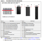
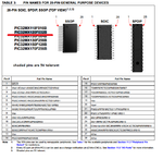
Now I am going to program PIC32MX220F032B, but it turns out that (according to datasheet) it has no 5V tolerant PGD/PGC pins!

Here is the comparison:
PIC32MX120F032B.png
PIC32MX220F032B.png
So now I am asking you guys, how can I get around this trouble? Do I understand correctly that MX220 version MUST be programmed with PGD/PGC signals at 3V level instead of 5V level like the MX120 version?
Is there any simple DIP chip that will convert 5V logic levels from my PICKIT clone to the 3V logic levels acceptable by MX220?
What is the direction of PGD and PGC lines? I assume that one is read and second write, but who knows?
Any suggestions appreciated!
 

So now I am asking you guys, how can I get around this trouble? Do I understand correctly that MX220 version MUST be programmed with PGD/PGC signals at 3V level instead of 5V level like the MX120 version?

If all the available PGC/PGD lines of a device are not 5V tolerant, then yes you will need to perform some voltage level translation. You also should be aware, that the High Voltage (Vpp) applied to MCLR during the programming of the device, varies from device family to device family as well. Therefore, you may want to consider picking up an inexpensive PICkit 3 clone.

Is there any simple DIP chip that will convert 5V logic levels from my PICKIT clone to the 3V logic levels acceptable by MX220?

There are a number of different ways to implement level shifting/voltage translation. I've attached a guide which contains several options, I keep a couple dozen or so breakout boards (BOBs) with TI's TXB0104 handy, which is a 4-bit bidirectional voltage translator, similar to the following:

SparkFun Voltage-Level Translator Breakout - TXB0104

I also have a dozen or so, simpler MOSFET based voltage level shifting BOBs like the following handy:

SparkFun Logic Level Converter - Bi-Directional

Unfortunately, most bidirectional voltage level translators are not available in a DIP package, so you'll need to find some BOB blanks to make your own for breadboarding.


What is the direction of PGD and PGC lines? I assume that one is read and second write, but who knows?

PGC is the unidirectional clock signal line which always emanates from the programmer during programming, PGD is a bidirectional data line, which the programmer first writes the firmware as a data stream and then uses the same line to read back the data/firmware and verify the programming was successful.

For programming, no clock is needed on the target device, but power must be supplied.
When programming, the debugger puts programming levels on VPP/MCLR,
sends clock pulses on PGC and serial data via PGD. To verify that the part has been
programmed correctly, clocks are sent to PGC and data is read back from PGD.
This conforms to the ICSP protocol of the device under development.

BigDog
 

Attachments

  • 3VTipsNTricks.pdf
    561.2 KB · Views: 89
  • txb0104.pdf
    1.3 MB · Views: 65
74HC4050 and 74HC125 buffer chips are used as converters. They are powered by 3 volts and will tolerate 5 volt logic levels on the inputs, converting 5 volt levels to 3 volts.

2N7000 mosfets, which are inexpensive, can be used, connected as below.
They are automatically bidirectional, 3 to 5, or 5 to 3 volts.

Simple voltage dividers using resistors are also used.

Each method has advantages and limitations, such as drive current and rise and fall times.
Check the requirements that are needed for your application.

2N7000 converter.jpg
 

74HC4050 and 74HC125 buffer chips are used as converters. They are powered by 3 volts and will tolerate 5 volt logic levels on the inputs, converting 5 volt levels to 3 volts.

Of course, a major issue with the 74HC4050 and the 74HC125 is they are unidirectional, which does not make them ideal for voltage translation of the PGD line.

Examples of similar MOSFET voltage level shifting are provided in the previously attached 3V Tips and Tricks guide.


BigDog
 

Status
Not open for further replies.

Similar threads

Part and Inventory Search

Welcome to EDABoard.com

Sponsor

Back
Top