Pheetuz
Full Member level 3
Good evening folks.
I have been starting work on a project using the microchip wifi modules along with a PIC18F96J60 as used on the PICDEM2.net demo board.
I have put together a circuit based loosely on the PICDEM2.net design and had it manufactured, I then only populated the microcontroller and associated circuitry such as the 10MHz crystal and associated capacitors and resistors. Please see the attached image to see what I have populated.

The power supplied to the circuit is at 3V3 and is working OK, the problem I am having is that when I connect the ICD3 to the circuit and MPLab tries to connect to the device I get the error message:
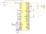
I cannot think what could be causing the error, I have tried shortening the paths from the ICD3 to the pins and also buzzed through from the pins to the RJ11 connector to see if that was the problem (I know the schematic does not show MCLR being connected to the RJ11 connector but I have manually put this in now), all to no avail.
I managed to find a few minutes at work the other day to stick a scope on the crystal to find that there is no clock signal to speak of, now I know that this is a problem in itself but as I understand it the device can still be programmed without the use of the crystal oscillator, just not debugged?
If anyone can think of anything that I am missing then it would be much appreciated! I have a feeling it is going to be something simple and I am going to kick myself when I figure it out!
I have checked and double checked and triple checked my connections from the ICD to the PIC are correct!
Many thanks,
Pheetuz.
I have been starting work on a project using the microchip wifi modules along with a PIC18F96J60 as used on the PICDEM2.net demo board.
I have put together a circuit based loosely on the PICDEM2.net design and had it manufactured, I then only populated the microcontroller and associated circuitry such as the 10MHz crystal and associated capacitors and resistors. Please see the attached image to see what I have populated.

The power supplied to the circuit is at 3V3 and is working OK, the problem I am having is that when I connect the ICD3 to the circuit and MPLab tries to connect to the device I get the error message:
Target Detected
ICD3Err0086: Target Device ID (00000000) does not match
expected Device ID (00001fa0). If you experience persistent
problems communicating, the ICD 3 test interface can be
used to help diagnose the problem.
I cannot think what could be causing the error, I have tried shortening the paths from the ICD3 to the pins and also buzzed through from the pins to the RJ11 connector to see if that was the problem (I know the schematic does not show MCLR being connected to the RJ11 connector but I have manually put this in now), all to no avail.
I managed to find a few minutes at work the other day to stick a scope on the crystal to find that there is no clock signal to speak of, now I know that this is a problem in itself but as I understand it the device can still be programmed without the use of the crystal oscillator, just not debugged?
If anyone can think of anything that I am missing then it would be much appreciated! I have a feeling it is going to be something simple and I am going to kick myself when I figure it out!
I have checked and double checked and triple checked my connections from the ICD to the PIC are correct!
Many thanks,
Pheetuz.