Continue to Site

Welcome to EDAboard.com

Welcome to our site! EDAboard.com is an international Electronics Discussion Forum focused on EDA software, circuits, schematics, books, theory, papers, asic, pld, 8051, DSP, Network, RF, Analog Design, PCB, Service Manuals... and a whole lot more! To participate you need to register. Registration is free. Click here to register now.

pic18f452 ADC problem

Status
Not open for further replies.

icefire91

Newbie level 6
Joined
Sep 2, 2011
Messages
11
Helped
0
Reputation
0
Reaction score
0
Trophy points
1,281
Activity points
1,351
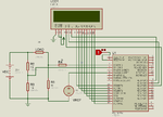
I have design a pic to measure Voltage and current together. it work perfectly normal on Proteus simulation. But when I fix it up to a bread board it does not work properly. I have two analogue input an0 and an1. an0 is for current and an1 is for voltage. so when i insert the wire from the current circuit into an0 the voltage and the current value displayed on the lcd is wrong. so when i remove the wire connected to an0, the current sensor, the voltage value display on the lcd is correct. Can anyone help me.
 

Hi

You should show us your connection diagram to see what could be wrong.

regards!
 

plc.png this is the diagram
 

Status
Not open for further replies.

Similar threads

Part and Inventory Search

Welcome to EDABoard.com

Sponsor

Back
Top