Continue to Site

Welcome to EDAboard.com

Welcome to our site! EDAboard.com is an international Electronics Discussion Forum focused on EDA software, circuits, schematics, books, theory, papers, asic, pld, 8051, DSP, Network, RF, Analog Design, PCB, Service Manuals... and a whole lot more! To participate you need to register. Registration is free. Click here to register now.

[SOLVED] PIC16F887 Port Problem

Status
Not open for further replies.

tahir4awan

Full Member level 4
Joined
Nov 29, 2010
Messages
208
Helped
16
Reputation
32
Reaction score
17
Trophy points
1,308
Location
Germany
Activity points
3,084
I am new to MIcrocontroller programming so I don't have much knowledge about advanced programming.
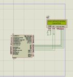
I was looking in MikroC manual for LCD output. I test the code, it worked fine but the problem is LCD pins are assigned on PORTB but when I assigned pins to PORTC and PORTD it didn't work.why?

What I learned about microcontrollers that all PORTS can be assigned as input and output then why it is only working on PORTB?

Please help
 

hi the problem in LCD configuring you must change it
if the lcd is connected to pic in port D so
sbit LCD_EN at RD5_bit; // Enable of lcd is connected to pin5 of port D
sbit LCD_D4 at RD0_bit;// D4 of lcd is connected to pin0 of port D
sbit LCD_D5 at RD1_bit;// D5 of lcd is connected to pin5 of port D
sbit LCD_D6 at RD2_bit;
sbit LCD_D7 at RD3_bit;
sbit LCD_RS_Direction at TRISD4_bit;// RS of lcd is connected to pin4 of port D
sbit LCD_EN_Direction at TRISD5_bit;
sbit LCD_D4_Direction at TRISD0_bit;
sbit LCD_D5_Direction at TRISD1_bit;
sbit LCD_D6_Direction at TRISD2_bit;
sbit LCD_D7_Direction at TRISD3_bit;

read comments

so you must reconfigure your LCD
 
I wrote the exact configuration but still it is not working. Did you test LCD on PORTD?
 

yes it works because

LCD EN is connected to RD5
LCD D4 is connected to RD0
LCD D5 is connected to RD 1
LCD D6 is connected to RD2
LCD D7 is connected to RD3

LCD RS is connected to RD4


so my configuration is
sbit LCD_EN at RD5_bit;
sbit LCD_D4 at RD0_bit;
sbit LCD_D5 at RD1_bit;
sbit LCD_D6 at RD2_bit;
sbit LCD_D7 at RD3_bit;
sbit LCD_RS_Direction at TRISD4_bit;
sbit LCD_EN_Direction at TRISD5_bit;
sbit LCD_D4_Direction at TRISD0_bit;
sbit LCD_D5_Direction at TRISD1_bit;
sbit LCD_D6_Direction at TRISD2_bit;
sbit LCD_D7_Direction at TRISD3_bit;

you need to make hardware connection in the simulation program like that i made in bold
it doesn't matter port d or Port B you use but configuration must be adjusted

if still there is problem i suggest you upload code file
 

This is the working code
---------------------------------------------------------------------------------------------------------------------------
// LCD module connections
sbit LCD_RS at RB4_bit;
sbit LCD_EN at RB5_bit;
sbit LCD_D4 at RB0_bit;
sbit LCD_D5 at RB1_bit;
sbit LCD_D6 at RB2_bit;
sbit LCD_D7 at RB3_bit;

sbit LCD_RS_Direction at TRISB4_bit;
sbit LCD_EN_Direction at TRISB5_bit;
sbit LCD_D4_Direction at TRISB0_bit;
sbit LCD_D5_Direction at TRISB1_bit;
sbit LCD_D6_Direction at TRISB2_bit;
sbit LCD_D7_Direction at TRISB3_bit;
// End LCD module connections

char txt1[] = "mikroElektronika";
char txt2[] = "EasyPIC6";
char txt3[] = "Lcd4bit";
char txt4[] = "example";

char i; // Loop variable

void main(){
ANSEL = 0; // Configure AN pins as digital I/O
ANSELH = 0;
C1ON_bit = 0; // Disable comparators
C2ON_bit = 0;

Lcd_Init(); // Initialize LCD

Lcd_Cmd(_LCD_CLEAR); // Clear display
Lcd_Cmd(_LCD_CURSOR_OFF); // Cursor off
Lcd_Out(1,6,txt3); // Write text in first row

Lcd_Out(2,6,txt4); // Write text in second row
Delay_ms(2000);
Lcd_Cmd(_LCD_CLEAR); // Clear display

Lcd_Out(1,1,txt1); // Write text in first row
Lcd_Out(2,5,txt2); // Write text in second row


}
-------------------------------------------------------------------------------------------------------------------------


I simply changed RB into RD. But Still not working
 

you code with changing D with instead of B and it works for PIC16f887

// LCD module connections
sbit LCD_RS at RD4_bit;
sbit LCD_EN at RD5_bit;
sbit LCD_D4 at RD0_bit;
sbit LCD_D5 at RD1_bit;
sbit LCD_D6 at RD2_bit;
sbit LCD_D7 at RD3_bit;

sbit LCD_RS_Direction at TRISD4_bit;
sbit LCD_EN_Direction at TRISD5_bit;
sbit LCD_D4_Direction at TRISD0_bit;
sbit LCD_D5_Direction at TRISD1_bit;
sbit LCD_D6_Direction at TRISD2_bit;
sbit LCD_D7_Direction at TRISD3_bit;
// End LCD module connections

char txt1[] = "mikroElektronika";
char txt2[] = "EasyPIC6";
char txt3[] = "Lcd4bit";
char txt4[] = "example";

char i; // Loop variable

void main(){
ANSEL = 0; // Configure AN pins as digital I/O
ANSELH = 0;
C1ON_bit = 0; // Disable comparators
C2ON_bit = 0;

Lcd_Init(); // Initialize LCD

Lcd_Cmd(_LCD_CLEAR); // Clear display
Lcd_Cmd(_LCD_CURSOR_OFF); // Cursor off
Lcd_Out(1,6,txt3); // Write text in first row

Lcd_Out(2,6,txt4); // Write text in second row
Delay_ms(2000);
Lcd_Cmd(_LCD_CLEAR); // Clear display

Lcd_Out(1,1,txt1); // Write text in first row
Lcd_Out(2,5,txt2); // Write text in second row


}


it works in protues simulation
see attached photo

i simply changed B with D

you may need to make sure that you are working with pic16f887
 

Attachments

  • itworks.JPG
    itworks.JPG
    32.1 KB · Views: 92
I create a new file in MikroC and now the code is working. Thanks for help
 

Status
Not open for further replies.

Similar threads

Part and Inventory Search

Welcome to EDABoard.com

Sponsor

Back
Top