Continue to Site

Welcome to EDAboard.com

Welcome to our site! EDAboard.com is an international Electronics Discussion Forum focused on EDA software, circuits, schematics, books, theory, papers, asic, pld, 8051, DSP, Network, RF, Analog Design, PCB, Service Manuals... and a whole lot more! To participate you need to register. Registration is free. Click here to register now.

[SOLVED] PIC16F887 Graphics LCD

Status
Not open for further replies.

tahir4awan

Full Member level 4
Joined
Nov 29, 2010
Messages
208
Helped
16
Reputation
32
Reaction score
17
Trophy points
1,308
Location
Germany
Activity points
3,084
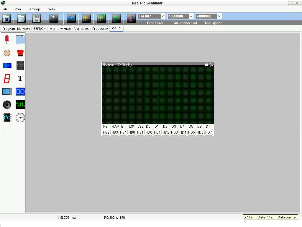
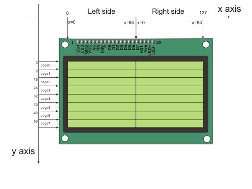
Hi guys I wrote this code to draw a simple vertical line. The problem is the line starts from center but I want line to be started from leftmost side.The GLCD is divided into two parts LEFT and RIGHT but in line command it is only started in right side.Can you help me solving this problem
----------------------------------------------------------------------------
char GLCD_DataPort at PORTD;

sbit GLCD_CS1 at RB0_bit;
sbit GLCD_CS2 at RB1_bit;
sbit GLCD_RS at RB2_bit;
sbit GLCD_RW at RB3_bit;
sbit GLCD_EN at RB4_bit;
sbit GLCD_RST at RB5_bit;

sbit GLCD_CS1_Direction at TRISB0_bit;
sbit GLCD_CS2_Direction at TRISB1_bit;
sbit GLCD_RS_Direction at TRISB2_bit;
sbit GLCD_RW_Direction at TRISB3_bit;
sbit GLCD_EN_Direction at TRISB4_bit;
sbit GLCD_RST_Direction at TRISB5_bit;


void main() {
ANSEL = 0;
ANSELH = 0;
C1ON_bit = 0;
C2ON_bit = 0;
Glcd_Init();
Glcd_Fill(0x00);

while(1) {

Glcd_Fill(0x00);
Glcd_V_Line(0, 60, 0, 1);

delay_ms(2000);


}
}

----------------------------------------------------------------------------
 

Come on Guys there has to be someone who can solve my problem.
 

Thank you, mehtadhaval and ckshivaram but my problem still exists. You said page option does that. Actually there are three options in MikroC
Glcd_Set_Side
Glcd_Set_X
Glcd_Set_Page

It is Set_Side option which selects left or right side. Set_X option selection dots within left or right side.Glcd_Set_Page selects from top to bottom because GLCD is divided into 8 pages from top to bottom. See the picture. I am not using specific company GLCD because I am testing the code on simulators. I checked my code both on REAL PIC SIMULATOR and PIC SIMULATOR IDE but both simulators are giving same result. According to the options above I told still GLCD is displaying line from center.
There is also a manual method to select left or right side. CS1 and CS2 selects left or right side.
CS1 = 1 and CS2 = 0 left side
CS1 = 0 and CS2 = 1 right side
But I don't thing that GLCD is designed to select right and left sides manually. The software does the job but unfortunately it is not working. Any suggestions.


mehtadhaval you can download MikroC User Manual by searching in Goolge. Its is 2MB pdf file.All thing are given in it.
 

I think, there should be no problem while directly using Glcd_V_Line(0, 60, 0, 1); command.

The Glcd_Set_Side,Glcd_Set_X and Glcd_Set_Page commands are for setting position when you need to read or write data from or to Glcd.

But still, try "glcd_Set_Side(0)" and then use the "Glcd_V_Line(0, 60, 0, 1)" command.

Also, try using the simple Glcd_Line(); command.
 
Thank you for your great help. I think it is not the code problem but the problem of the simulator. Simulators don't support all compilers 100%. Like there is problem in REAL PIC SIMULATOR to read/write I2C EEPROM while the same code is working on PIC SIMULATOR IDE. I am 100% sure simulator is causing the problem.
 

Yes I was right Mehta it is the problem of the Simulator. I checked my program on ISIS Proteus and it worked like a charm. Anyway thanks for your great help and interest.
 

Status
Not open for further replies.

Similar threads

Part and Inventory Search

Welcome to EDABoard.com

Sponsor

Back
Top