Continue to Site

Welcome to EDAboard.com

Welcome to our site! EDAboard.com is an international Electronics Discussion Forum focused on EDA software, circuits, schematics, books, theory, papers, asic, pld, 8051, DSP, Network, RF, Analog Design, PCB, Service Manuals... and a whole lot more! To participate you need to register. Registration is free. Click here to register now.

[PIC] PIC16F88 internal oscillator problem

Status
Not open for further replies.

buffallo

Member level 1
Joined
Mar 2, 2012
Messages
38
Helped
3
Reputation
6
Reaction score
3
Trophy points
1,288
Activity points
1,637
Hi all,

probably you are all tired of reading such threads, so am I.

The issue is as follows:
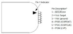
I had a schematic for a voltage meter using the 16f88. I printed the results on a 7segment LED displays
and used the internal ADC module. I also used the internal oscillator!
The circuit worked well, but I needed the chip for something else to try.

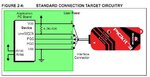
However, some days ago I got my pickit 3 and decided to put back the original voltage meter program on the chip.
I attached the pickit as a programmer and burned the code into the 16f88. However, the circuit wouldnt work now.

My code is as follows:

Code:
LIST   P=PIC16F88

          #include        <p16f88.inc>

 
          __CONFIG  _CONFIG1, _CCP1_RB0&_LVP_OFF&_MCLR_OFF&_PWRTE_ON&_WDT_OFF&_INTRC_IO
          __CONFIG  _CONFIG2, _IESO_OFF & _FCMEN_OFF

	errorlevel	-302 
	errorlevel	-207

	org		0x00	

	goto 	setup
	org		0x04	
	goto		setup
setup

	bsf     STATUS,RP0      ; bank 1     
        clrf    ANSEL           

        movlw   b'01110000' 
        movwf   OSCCON          ; select 8-MHz INTOSC clock      
 Stable  btfss   OSCCON,IOFS   
        goto    Stable        
        bcf     STATUS,RP0      ; bank 0

But something is wrong, i.e. nothing happens. I tried all sorts of configuration bits and OSCCON IRCF bit settings - nothing changes.
ONLY when I write 000 to the IRCF bits the circuit works (in 31.25 kHz). Trying to modify the bits in steps (i.e. one bit at a time) didn't work either.

Also if I try to debug the code, I reach teh line movwf OSCCON and I get an unknown error from the pickit.

So please, folks, bring me out of my misery! I like this chip very much, but this is very frustrating. I have lost 2 days of my life dealing with it and I don't know how much more I can last.

Thanks,
Dimitar
 

The System Clock Select bits, SCS1:SCS0, select the clock source that is used when the device is operating in power-managed modes. When the bits are cleared (SCS<1:0> = 00), the system clock source comes from the main oscillator that is selected by the FOSC2:FOSC0 configuration bits in Configuration Word 1 register. When the bits are set in any other manner, the system clock source is provided by the Timer1 oscillator (SCS1:SCS0 = 01) or from the
internal oscillator block (SCS1:SCS0 = 10). After a Reset, SCS<1:0> are always set to ‘00’. The Internal Oscillator Select bits, IRCF2:IRCF0, select the frequency output of the internal oscillator block that is used to drive the system lock. The choices are the INTRC source (31.25 kHz), the INTOSC source (8 MHz) or one of the six frequencies derived from the INTOSC postscaler (125 kHz to 4 MHz). Changing the configuration of these bits has an immediate change on
the multiplexor’s frequency output.The OSTS and IOFS bits indicate the status of the primary oscillator and INTOSC source; these bits are set when their respective oscillators are stable. In particular, OSTS indicates that the Oscillator Start-up Timer has timed out.

Please go through this part of datasheet .. i suppose u need set the clock source SCS =1 or in config FOSC2:FOSC0 ..set this .

Check for startup OSTS flag u can read it and wait till the clock source is stable .
 

Hi,

This code flashes PortB every 2 seconds, see if it works?
 

Attachments

  • F88flash.zip
    266 bytes · Views: 75

Hi,

thanks for the example, I will check it out and we'll se if the issue is still present.

Thanks!
 

Hi,

I tried the code, but still I have the same problem - nothing happens.... It seems that any change of the OSCCON register results in faulty operation of the microcontroller.

Any further suggestions are welcome.

EDIT: It looks like any attempt to modify the IRCF bits brings the chip to a stall. Could that be an issue related to the sillicon, or has anyone else expirienced that. I also tried to change the contents of the OSCCON register indirectly (FSR/INDF), but the result was the same. What am I missing?
 
Last edited:

Hi,

That .hex code I sent was run on a simulator ok.

However in case I got something wrong that the simulator did not pick up I found an old F88 and simply programmed it up in an ic socket with my Pk2.

It works fine, Port B on and off every 2 seconds.

When you programmed my .hex file with your Pk3 did you manually enter any Config parameters ? ( all those needed were in the .hex code)
Have you any other circuitry connected to the F88 ?

I just have mine in that ic socket with the Pk2 connected, nothing else, I just enable Vdd to allow it to run ( check your Mclre state ) and measured PortB with a multimeter to show its working.

If you cannot so the same , have you tried a new chip ?
 

Hi,

the worst part is that I do not have another F88 chip.

I have not entered any other config parameters after your code, but still it didn't work.

Now I am trying with the following code:

Code:
setup
	banksel TRISA
	clrf		TRISA
	clrf		TRISB

	call		blinkk      ; function that blinks portB with some delay
 	call		blinkk
	
	banksel OSCCON
 
 	movlw	OSCCON
 	
 	movwf	FSR
 	
        movlw   b'00010010'     ; All kinds of combos are tried here, 
        movwf   INDF              
        nop
        nop
  
 	call		blinkk    
	
	call		BDelay

	banksel	BANK_0

	goto 	setup

So after I burn that code I see two flashes of the diode at very slow rate (assuming that it's running at 31.25kHz). Then the LED stalls at the last state. I assume something is wrong with the chip but I want to be pretty sure of that, because when I comment out the lines which change the contents of OSCCON register (i.e. I keep it running at 31.25kHz) the original voltage meter program runs just fine (althogh slow) and the ADC module, ports, timers work just fine.


Hi,

Won't get chance to try your code until i get back in, here is the source code I used ok.

Code:
		LIST   P=PIC16F88

          #include        <p16f88.inc>

 
          __CONFIG  _CONFIG1, _CCP1_RB0&_LVP_OFF&_MCLR_OFF&_PWRTE_ON&_WDT_OFF&_INTRC_IO
          __CONFIG  _CONFIG2, _IESO_OFF & _FCMEN_OFF
			errorlevel	-302 
			errorlevel	-207


		cblock 0X20			; specify user regiaters
		d1
		d2
		d3
		COUNT
		endc

		org		0x00	

		goto 	setup
		org		0x04	
		retfie

setup
		banksel	ANSEL  
        clrf    ANSEL           

        movlw   b'01110010' 
        movwf   OSCCON          ; select 8-MHz INTOSC clock      
 Stable btfss   OSCCON,IOFS   
        goto    Stable        
        banksel 0			    ; bank 0
;       progam to flash all of PortB pins on and off every 2 seconds

		CLRF	PORTB		; Set portb,c,d to digital outputs
	
		BANKSEL TRISB
		CLRF	TRISB
		BANKSEL 0


LOOP						; main program loo[
		CALL	DELAY2s
		MOVLW   0xFF
		MOVWF	PORTB		; Set  port HIGH

		CALL	DELAY2s

		MOVLW   0x00
		MOVWF	PORTB		; Set  port LOW
		GOTO	LOOP		

	
DELAY2s						; 2 SECOND DELAY with 8mhz clock
		movlw	0x23
		movwf	d1
		movlw	0xB9
		movwf	d2
		movlw	0x09
		movwf	d3
Delay_0
		decfsz	d1, f
		goto	dly1
		decfsz	d2, f
dly1	goto	dly2
		decfsz	d3, f
dly2	goto	Delay_0
		return

		END
 

Hi,

Have you been able to compile and program the code I sent ? - does it work ?
If not, perhaps you should show the circuit you are using it in as something might be affecting its running.

The code you posted, no idea what you are trying to do with the FSR and INCF an OSCON- seems all wrong.
If you post your whole code if might be easier to see whats happening.

Have you got any other pic chips at all ?


Code C - [expand]
1
__CONFIG  _CONFIG1, _CCP1_RB0&_LVP_ON&_MCLR_OFF&_PWRTE_OFF&_WDT_OFF&_INTRC_IO


Enable LVP if you are programming using PICKit2 without providing external voltage to the device. PICKit2 will provide the Vpp.
 

Hi,

I am using pickit 3 and I have not connected the LVP pin, should I connect it to the pic when using _LVP_ON ?
 

If you are not providing external voltage to the micro while programming then PICKit3 will provide the voltages needed. You should set LVP ON in config words. See images. PICKit3 connections should be like below.


If INTRC1 is used then set


Code ASM - [expand]
1
2
3
4
5
6
7
8
OSCON = 0x66
 
or 
 
0x6E
 
ANSEL = 0x00;
CMCON = 0x07


97459d1382176895-icsp.jpg


97458d1382176894-6-pin-icsp-pinout.jpg
 

Attachments

  • 6-pin-ICSP-pinout.jpg
    6-pin-ICSP-pinout.jpg
    20.3 KB · Views: 120
  • icsp.JPG
    icsp.JPG
    27.4 KB · Views: 118
Last edited:

Hi,

Don't know why Jayanth is advocating LVP when he only shows ICSP HV diagrams.

Would suggest you stick to the standard HV methods, which means your Config should be LVP=OFF.

For LVP to be invoked you also need the PMG/RB3 pin 9 taken high.

However this is a clue as to why your HV programming may not work. Even if LVP=OFF , on some of the older microchips if the PGM pin is left floating then it can assume its trying to do a lvp instead of HV.
To ensure you avoid this put a 10k resistor from pin 9 to 0v.
 

Hi guys,

I think we are straying off the topic.

I manage to program the chip just fine. I have prepared a 'blink-a-LED' program, and no matter LVP_OFF or LVP_ON the program is loaded correctly. However, when the chip reaches the instruction

Code:
movwf OSCCON

the pic hangs (i.e. the LED stops blinking and remains in it's last state).

If I comment out this line of code the LED blinks forever, which indicates that the code is working just fine. As I mentioned above, the original program is working fine, but very slow (due to the 31.25kHz INTRC).

The thing is that whenever I try to modify the IRCF bits in the OSCCON register the chip just 'hangs'. I read the datasheets/errata and so on, but everywhere it is stated that ' ... you can modify the IRCF bits at any time ...'.

If you've had similar bad experiences, please let me know if there is a workaround (except for buying another chip) :)

Regards
Dimitar
 

OSCON value is wrong. Use OSCON = 0x76 for 8 MHz internal RC oscillator. Why do you want to modify IRCF bit after initialization? Don't modify OSCON after entering the blink loop.
 

Hi,

Seems you are running your program via Debugger , yes ?

What happens if you just program the chip and then Run the program without the PK3 / Debugger connected - does My program work then.

You never answered the previous question if anything else is connected to the F88 , assuming its in a circuit board ?

As Jayanth says and like my code shows you really need to set OSCCON as the first instruction.


Jayanth,

Can see the Pk3 uses pin 6 for LVP, though not really detailed in the Pk3 user manual.

However, never heard anything about the Pk2 being able to control the LVP from its pin 6 which I only knew was good as an input to its logic analyzer function, any info would be appreciated.

thanks
 

Hi again,

I redesigned the schematic so that a crystal is used instead of the internal oscillator. Everything wokrs just fine now.
This leads me to the conclusion that there is something wrong with this particular chip (i.e. the internals are damaged).

Another couple of days wasted!
 

Hi,

Would think it unlikely just the internal osc is damaged, more likely something wrong with your code.

Short of getting another chip, if you post the code your 'internal' version I could try running it my F88 chip.
 

An External oscillator is installed within the microcontroller and connected to the OSC1 and OSC2 pins. It is called “external” because it relies on external circuitry for the clock signal and frequency stabilization, such as a stand-alone oscillator, quarts crystal, ceramic resonator or resistor-capacitor circuit. The oscillator mode is selected by bits of bytes sent during programming, so called Config Word.

Internal oscillator consists of two separate, internal oscillators:

The HFINTOSC is a high-frequency internal oscillator which operates at 8MHz. The microcontroller can use clock source generated at that frequency or after being divided in prescaler; and

The LFINTOSC is a low-frequency internal oscillator which operates at 31 kHz. Its clock sources are used for watch-dog and power-up timing but it can also be used as a clock source for the operation of the entire microcontroller.

The system clock can be selected between external or internal clock sources via the System Clock Select (SCS) bit of the OSCCON register.
 

Status
Not open for further replies.

Similar threads

Part and Inventory Search

Welcome to EDABoard.com

Sponsor

Back
Top