Continue to Site

Welcome to EDAboard.com

Welcome to our site! EDAboard.com is an international Electronics Discussion Forum focused on EDA software, circuits, schematics, books, theory, papers, asic, pld, 8051, DSP, Network, RF, Analog Design, PCB, Service Manuals... and a whole lot more! To participate you need to register. Registration is free. Click here to register now.

[SOLVED] PIC16F877A USART Transmitting

Status
Not open for further replies.

jjeevan007

Full Member level 5
Joined
Apr 13, 2012
Messages
310
Helped
44
Reputation
88
Reaction score
43
Trophy points
1,308
Location
bangalore
Activity points
2,782
Hi to all,

i am trying to transmit the Data from PIC16F877A to PC using serial communication with following code.


Code:


Code C - [expand]
1
2
3
4
5
6
7
8
9
10
11
12
13
14
15
16
17
18
19
20
21
22
23
24
25
26
27
28
29
30
31
32
33
34
35
36
37
38
39
40
41
42
43
44
45
46
47
48
49
50
51
52
53
54
55
56
57
58
59
60
61
62
63
64
65
66
67
68
69
70
71
72
73
74
75
76
77
78
79
#include<htc.h>
#include<pic.h>
//#include <pic16f877a.h>
#define _XTAL_FREQ 4000000
 
 
__CONFIG(0x1f3a); 
 
 
void main(void)
{
 
ADCON1 =0x06 ;      // Changes PORTA and PORTE to digital
TRISA = 0x00 ;      // Configure PORTA as output
TRISD = 0X00 ;      // Configure PORTD as output
TRISB = 0x00 ;      // Configure PORTB as output
TRISC = 0x00 ;      // Configure PORTC as output
TRISE = 0x00 ;      // Configure PORTE as output
 
 
SPBRG=25;           //setting the Baud Rate
RCSTA=0X80;         //Enabling the Serial Communication
TXSTA=0X26;         //Enabling Transmission in Serial Communication, Selecting Mode and Speed
 
TXREG='H';
while(TXIF==0 || TRMT==0);
 
TXREG='E';
while(TXIF==0 || TRMT==0);
 
TXREG='L';
while(TXIF==0 || TRMT==0);
 
TXREG='L';
while(TXLIF==0 || TRMT==0);
 
TXREG='O';
while(TXIF==0 || TRMT==0);
 
TXREG=' ';
while(TXIF==0 || TRMT==0);
 
TXREG='T';
while(TXIF==0 || TRMT==0);
 
TXREG='E';
while(TXIF==0 || TRMT==0);
 
TXREG='C';
while(TXIF==0 || TRMT==0);
 
TXREG='H';
while(TXIF==0 || TRMT==0);
 
TXREG='N';
while(TXIF==0 || TRMT==0);
 
TXREG='O';
while(TXIF==0 || TRMT==0);
 
TXREG='L';
while(TXIF==0 || TRMT==0);
 
TXREG='O';
while(TXIF==0 || TRMT==0);
 
TXREG='G';
while(TXIF==0 || TRMT==0);
 
TXREG='Y';
while(TXIF==0 || TRMT==0);


while(1);
 
}


the problem is i am facing is the message "HELLO TECHNOLOGY" is receiving continuously
anyone help me so that it should send the message only once.....

Complier used is HI-TECH complier.


regards
jeevan
 
Last edited by a moderator:
Hi to all,

i am trying to transmit the Data from PIC16F877A to PC using serial communication with following code.


Code:


Code C - [expand]
1
2
3
4
5
6
7
8
9
10
11
12
13
14
15
16
17
18
19
20
21
22
23
24
25
26
27
28
29
30
31
32
33
34
35
36
37
38
39
40
41
42
43
44
45
46
47
48
49
50
51
52
53
54
55
56
57
58
59
60
61
62
63
64
65
66
67
68
69
70
71
72
73
74
75
76
77
78
79
#include<htc.h>
#include<pic.h>
//#include <pic16f877a.h>
#define _XTAL_FREQ 4000000
 
 
__CONFIG(0x1f3a); 
 
 
void main(void)
{
 
ADCON1 =0x06 ;      // Changes PORTA and PORTE to digital
TRISA = 0x00 ;      // Configure PORTA as output
TRISD = 0X00 ;      // Configure PORTD as output
TRISB = 0x00 ;      // Configure PORTB as output
TRISC = 0x00 ;      // Configure PORTC as output
TRISE = 0x00 ;      // Configure PORTE as output
 
 
SPBRG=25;           //setting the Baud Rate
RCSTA=0X80;         //Enabling the Serial Communication
TXSTA=0X26;         //Enabling Transmission in Serial Communication, Selecting Mode and Speed
 
TXREG='H';
while(TXIF==0 || TRMT==0);
 
TXREG='E';
while(TXIF==0 || TRMT==0);
 
TXREG='L';
while(TXIF==0 || TRMT==0);
 
TXREG='L';
while(TXLIF==0 || TRMT==0);
 
TXREG='O';
while(TXIF==0 || TRMT==0);
 
TXREG=' ';
while(TXIF==0 || TRMT==0);
 
TXREG='T';
while(TXIF==0 || TRMT==0);
 
TXREG='E';
while(TXIF==0 || TRMT==0);
 
TXREG='C';
while(TXIF==0 || TRMT==0);
 
TXREG='H';
while(TXIF==0 || TRMT==0);
 
TXREG='N';
while(TXIF==0 || TRMT==0);
 
TXREG='O';
while(TXIF==0 || TRMT==0);
 
TXREG='L';
while(TXIF==0 || TRMT==0);
 
TXREG='O';
while(TXIF==0 || TRMT==0);
 
TXREG='G';
while(TXIF==0 || TRMT==0);
 
TXREG='Y';
while(TXIF==0 || TRMT==0);


while(1);
 
}


the problem is i am facing is the message "HELLO TECHNOLOGY" is receiving continuously
anyone help me so that it should send the message only once.....

Complier used is HI-TECH complier.


regards
jeevan

The possible reason of this may be that, you haven't turned off your watch dog timer..
If you have not turned of your watch dog timer off then turn it off.
It will solve the problem.
 

i have turned off the watch dog timer...........
plz help me........
 

i have turned off the watch dog timer...........


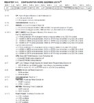
You do not appear to have the correct value for Configuration Register setting.

How are you obtaining the value of 0x1f3a?

For a PIC16F877A the first digit can only be either a 0 or 2, not 1.

Have you mistakenly referred to the PIC16F877 datasheet, as it is not the same as PIC16F877A datasheet?


PIC16F877AConfigRegister.jpg


I would strongly recommend you use the predefined macros to set the Configuration Register.

Replace this:

Code:
__CONFIG(0x2F0A);

With this:

Code:
__CONFIG(FOSC_HS & WDTE_OFF & PWRTE_ON & BOREN_OFF & LVP_OFF & CPD_OFF & WRT_OFF & DEBUG_ON & CP_OFF);


The predefined Configuration Register bitmasks are available in the device specific header file, in this case pic16f877a.h.
Code:
#ifndef	_HTC_H_
#warning Header file pic16f877a.h included directly. Use #include <htc.h> instead.
#endif

/* header file for the MICROCHIP PIC microcontroller
 *  16F877A
 */


#ifndef __PIC16F877A_H
#define __PIC16F877A_H

//
// Configuration mask definitions
//


// Config Register: CONFIG
#define CONFIG               0x2007
// Oscillator Selection bits
// RC oscillator
#define FOSC_EXTRC           0xFFFF
// HS oscillator
#define FOSC_HS              0xFFFE
// XT oscillator
#define FOSC_XT              0xFFFD
// LP oscillator
#define FOSC_LP              0xFFFC
// Watchdog Timer Enable bit
// WDT enabled
#define WDTE_ON              0xFFFF
// WDT disabled
#define WDTE_OFF             0xFFFB
// Power-up Timer Enable bit
// PWRT disabled
#define PWRTE_OFF            0xFFFF
// PWRT enabled
#define PWRTE_ON             0xFFF7
// Brown-out Reset Enable bit
// BOR enabled
#define BOREN_ON             0xFFFF
// BOR disabled
#define BOREN_OFF            0xFFBF
// Low-Voltage (Single-Supply) In-Circuit Serial Programming Enable bit
// RB3/PGM pin has PGM function; low-voltage programming enabled
#define LVP_ON               0xFFFF
// RB3 is digital I/O, HV on MCLR must be used for programming
#define LVP_OFF              0xFF7F
// Data EEPROM Memory Code Protection bit
// Data EEPROM code protection off
#define CPD_OFF              0xFFFF
// Data EEPROM code-protected
#define CPD_ON               0xFEFF
// Flash Program Memory Write Enable bits
// Write protection off; all program memory may be written to by EECON control
#define WRT_OFF              0xFFFF
// 0000h to 00FFh write-protected; 0100h to 1FFFh may be written to by EECON control
#define WRT_256              0xFDFF
// 0000h to 07FFh write-protected; 0800h to 1FFFh may be written to by EECON control
#define WRT_1FOURTH          0xFBFF
// 0000h to 0FFFh write-protected; 1000h to 1FFFh may be written to by EECON control
#define WRT_HALF             0xF9FF
// In-Circuit Debugger Mode bit
// In-Circuit Debugger disabled, RB6 and RB7 are general purpose I/O pins
#define DEBUG_OFF            0xFFFF
// In-Circuit Debugger enabled, RB6 and RB7 are dedicated to the debugger
#define DEBUG_ON             0xF7FF
// Flash Program Memory Code Protection bit
// Code protection off
#define CP_OFF               0xFFFF
// All program memory code-protected
#define CP_ON                0xDFFF

Also you no longer need:

Code:
#include<pic.h>

Just:

Code:
#include<htc.h>


BigDog
 

i have load the Configuration register with 0x2f0a valve, but the still the problem is not solved.................


jeevan
 

I managed to compile the following version of your code and execute it on a PIC16F877A, the output was a single non repetitive line:

jjeevan007.jpg

Therefore the issue does not appear to be code based.

Perhaps the issue is due to a power supply, EMI or other hardware related cause.

Have you utilized an appropriate bypass capacitor between Vdd (5V) and Vss (GND) as close to the PIC pins as possible?

Can you post a schematic of the actual circuit?


Code C - [expand]
1
2
3
4
5
6
7
8
9
10
11
12
13
14
15
16
17
18
19
20
21
22
23
24
25
26
27
28
29
30
31
32
33
34
35
36
37
38
39
40
41
42
43
44
45
46
47
48
49
50
51
52
53
54
55
56
57
58
59
60
61
62
63
64
65
66
67
68
69
70
71
72
73
74
75
76
77
78
#include<htc.h>
 
#define _XTAL_FREQ 4000000
 
 
__CONFIG(FOSC_HS & WDTE_OFF & PWRTE_ON & BOREN_OFF & LVP_OFF & CPD_OFF & WRT_OFF & DEBUG_ON & CP_OFF);
 
 
void main(void)
{
 
    ADCON1 =0x06 ;      // Changes PORTA and PORTE to digital
    TRISA = 0x00 ;      // Configure PORTA as output
    TRISD = 0X00 ;      // Configure PORTD as output
    TRISB = 0x00 ;      // Configure PORTB as output
    TRISC = 0x00 ;      // Configure PORTC as output
    TRISE = 0x00 ;      // Configure PORTE as output
 
 
    SPBRG=25;           //setting the Baud Rate
    RCSTA=0X80;         //Enabling the Serial Communication
    TXSTA=0X26;         //Enabling Transmission in Serial Communication, Selecting Mode and Speed
 
    TXREG='H';
    while(TXIF==0 || TRMT==0);
 
    TXREG='E';
    while(TXIF==0 || TRMT==0);
 
    TXREG='L';
    while(TXIF==0 || TRMT==0);
 
    TXREG='L';
    while(TXIF==0 || TRMT==0);
 
    TXREG='O';
    while(TXIF==0 || TRMT==0);
 
    TXREG=' ';
    while(TXIF==0 || TRMT==0);
 
    TXREG='T';
    while(TXIF==0 || TRMT==0);
 
    TXREG='E';
    while(TXIF==0 || TRMT==0);
 
    TXREG='C';
    while(TXIF==0 || TRMT==0);
 
    TXREG='H';
    while(TXIF==0 || TRMT==0);
 
    TXREG='N';
    while(TXIF==0 || TRMT==0);
 
    TXREG='O';
    while(TXIF==0 || TRMT==0);
 
    TXREG='L';
    while(TXIF==0 || TRMT==0);
 
    TXREG='O';
    while(TXIF==0 || TRMT==0);
 
    TXREG='G';
    while(TXIF==0 || TRMT==0);
 
    TXREG='Y';
    while(TXIF==0 || TRMT==0);


    while(1);
 
}


BigDog
 
You need bypass capacitors, 0.1uF is a common value, between Vdd and Vss as close to the PIC as possible.


Is the power supply well regulated?


BigDog
 

Sorry Friends
the problem was in max232 ic

thanks for all helping
 

Status
Not open for further replies.

Similar threads

Part and Inventory Search

Welcome to EDABoard.com

Sponsor

Back
Top