illegal121
Member level 2
yes i think You are rite.. I use 10 ms delay during that 6 times high /low on port B , but LEDes are not blinking with the same delay as specified they are blinking with their wish.. 
Follow along with the video below to see how to install our site as a web app on your home screen.
Note: This feature may not be available in some browsers.
I am using FIXED 5V ..
I tried 20Mhz and 11Mhz..
One other thing have you installed a 100nF capacitor across the Vdd and Vss pins (5v to GND), keeping it a close as possible to the PIC?
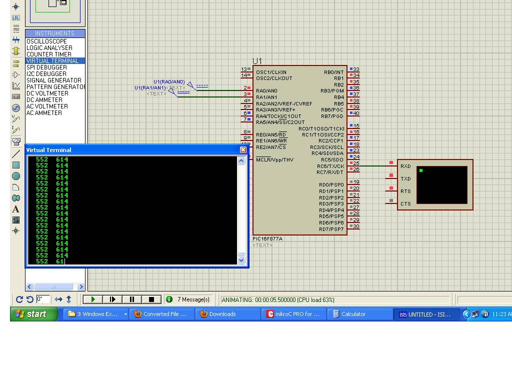
UART1_Write(13);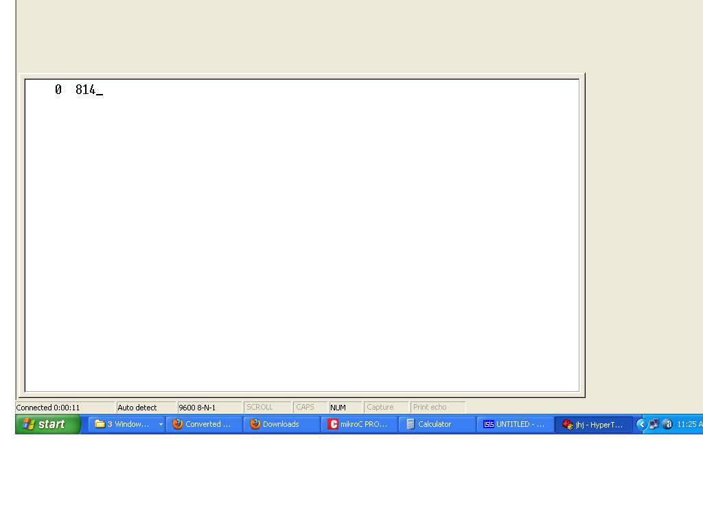
but in real hype terminal it is overwriting the same first line continuously..