Continue to Site

Welcome to EDAboard.com

Welcome to our site! EDAboard.com is an international Electronics Discussion Forum focused on EDA software, circuits, schematics, books, theory, papers, asic, pld, 8051, DSP, Network, RF, Analog Design, PCB, Service Manuals... and a whole lot more! To participate you need to register. Registration is free. Click here to register now.

pic16f877 i2c lcd problem

Status
Not open for further replies.

mugur

Newbie level 4
Newbie level 4
Joined
Nov 21, 2012
Messages
7
Helped
0
Reputation
0
Reaction score
0
Trophy points
1,281
Visit site
Activity points
1,336
Hi guys. I am a beginner in c programming and I try to connect a 20x4 lcd to a pic16f877 through i2c module. The lcd is working if I connect it directly to pic. The i2c module is a cheap one from ebay, a mjkdz model like **broken link removed**. I have the code but my problem is that I can't make it work because I need to change the address. The initial address is 0xc6 and I need to change it to 0x20 or 0x27. The code is below:

Code:
#include <pic.h>
#include <stdio.h>
	 
__CONFIG(0x3b32);		

void clrscn(void);				// prototypes
void cursor(char pos);
void print(char *p);
void setup(void);

char s[21];						// buffer used to hold text to print

void main(void)
{
	setup();					// sets up the PIC16F877 I2C port
	clrscn();					// clears the LCD03 disply
	cursor(26);					// sets cursor to center the text on 2nd row of LCD03
	sprintf(s,"Hello World");	// Traditional welcome text, printed into our buffer
	print(s);					// send it to the LCD03

	while(1);					// just stops
}


void clrscn(void)
{
	SEN = 1;					// send start bit
	while(SEN);					// and wait for it to clear

	SSPIF = 0;
	SSPBUF = 0xc6;				// LCD02 I2C address
	while(!SSPIF);				// wait for interrupt
	SSPIF = 0;					// then clear it.

	SSPBUF = 0;					// address of register to write to 
	while(!SSPIF);				// 
	SSPIF = 0;					//

	SSPBUF = 12;				// clear screen 
	while(!SSPIF);				// 
	SSPIF = 0;					//

	SSPBUF = 4;					// cursor off 
	while(!SSPIF);				// 
	SSPIF = 0;					//
	 
	PEN = 1;					// send stop bit
	while(PEN);					//
}

		
void cursor(char pos)
{
	SEN = 1;					// send start bit
	while(SEN);					// and wait for it to clear

	SSPIF = 0;
	SSPBUF = 0xc6;				// LCD02 I2C address
	while(!SSPIF);				// wait for interrupt
	SSPIF = 0;					// then clear it.

	SSPBUF = 0;					// address of register to write to 
	while(!SSPIF);				// 
	SSPIF = 0;					//

	SSPBUF = 2;					// set cursor 
	while(!SSPIF);				// 
	SSPIF = 0;					//
	SSPBUF = pos;				//  
	while(!SSPIF);				// 
	SSPIF = 0;					//
	 
	PEN = 1;					// send stop bit
	while(PEN);					//
}

		
void print(char *p)
{
	SEN = 1;					// send start bit
	while(SEN);					// and wait for it to clear

	SSPIF = 0;
	SSPBUF = 0xc6;				// LCD02 I2C address
	while(!SSPIF);				// wait for interrupt
	SSPIF = 0;					// then clear it.

	SSPBUF = 0;					// address of register to write to 
	while(!SSPIF);				// 
	SSPIF = 0;					//

	while(*p) {
		SSPBUF = *p++;			// write the data 
		while(!SSPIF);			// 
		SSPIF = 0;				// 
	}

	PEN = 1;					// send stop bit
	while(PEN);					//
}


void setup(void)
{
unsigned long x;

	TRISC = 0xff;
	PORTC = 0xff;

	SSPSTAT = 0x80;
	SSPCON = 0x38;
	SSPCON2 = 0x00;
	SSPADD = 50;				// SCL = 91khz with 20Mhz Osc

	for(x=0; x<60000; x++);		// wait for LCD03 to initialise
		
}

I tryed to replace "SSPBUF = 0xc6;" with "SSPBUF = 0x20;" or "SSPBUF = 0x27;" but so far no luck:cry:. Do I need to change something else in code or this should be enough?
I tryed to put 4.7k pull up resistors on SDA and SCL but is not working.

Please help me. Thank you.
 
Last edited:

Have you correctly modified the jumpers on the back of the I2C adapter board to reflect the new address?

Apparently you have a slightly different board then the one you've provided the link to on eBay as its default address is 0x27 and doesn't support the 0xC6 address.

Can you upload or provide a link for the user manual for your particular device?

BigDog
 

Thank you for your quick response. I have the exact module that is in the ebay link and I want to modify the address in my source code from 0xc6 to 0x27. My question was if it's enough to modify from "SSPBUF = 0xc6;" to "SSPBUF = 0x27;" or do I need to do something more. I do not have a manual for this but I think that the chip on the board is PCF8574. You can find .pdf of this chip **broken link removed**.
 

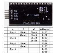
The address on an I2C device is typically set by the physical configuration of several address lines, pulling them high or pulling them low.

Your particular module has three jumpers on the back of the device, A, B and C which must be either opened or closed to properly configure the required I2C address.


Once the jumpers are properly configured you can then modify the address in the code to reflect the new address of the device.

According to the information provided in the above image and eBay listing the devices default address is 0x27, not 0xC6, and supports address in the 0x20 to 0x27 range.

You will need the pullups on the both SCL and SDA lines to properly communicate with the module.


BigDog
 

I did not touch the jumpers, they are open, so the address should be 0x27.
I put pullups (4.7k) on both SCL and SDA lines and i modified the code:
Code:
#include <pic.h>
#include <stdio.h>
	 
__CONFIG(0x3b32);		

void clrscn(void);				// prototypes
void cursor(char pos);
void print(char *p);
void setup(void);

char s[21];						// buffer used to hold text to print

void main(void)
{
	setup();					// sets up the PIC16F877 I2C port
	clrscn();					// clears the LCD03 disply
	cursor(26);					// sets cursor to center the text on 2nd row of LCD03
	sprintf(s,"Hello World");	// Traditional welcome text, printed into our buffer
	print(s);					// send it to the LCD03

	while(1);					// just stops
}


void clrscn(void)
{
	SEN = 1;					// send start bit
	while(SEN);					// and wait for it to clear

	SSPIF = 0;
	SSPBUF = 0x27;				// LCD02 I2C address
	while(!SSPIF);				// wait for interrupt
	SSPIF = 0;					// then clear it.

	SSPBUF = 0;					// address of register to write to 
	while(!SSPIF);				// 
	SSPIF = 0;					//

	SSPBUF = 12;				// clear screen 
	while(!SSPIF);				// 
	SSPIF = 0;					//

	SSPBUF = 4;					// cursor off 
	while(!SSPIF);				// 
	SSPIF = 0;					//
	 
	PEN = 1;					// send stop bit
	while(PEN);					//
}

		
void cursor(char pos)
{
	SEN = 1;					// send start bit
	while(SEN);					// and wait for it to clear

	SSPIF = 0;
	SSPBUF = 0x27;				// LCD02 I2C address
	while(!SSPIF);				// wait for interrupt
	SSPIF = 0;					// then clear it.

	SSPBUF = 0;					// address of register to write to 
	while(!SSPIF);				// 
	SSPIF = 0;					//

	SSPBUF = 2;					// set cursor 
	while(!SSPIF);				// 
	SSPIF = 0;					//
	SSPBUF = pos;				//  
	while(!SSPIF);				// 
	SSPIF = 0;					//
	 
	PEN = 1;					// send stop bit
	while(PEN);					//
}

		
void print(char *p)
{
	SEN = 1;					// send start bit
	while(SEN);					// and wait for it to clear

	SSPIF = 0;
	SSPBUF = 0x27;				// LCD02 I2C address
	while(!SSPIF);				// wait for interrupt
	SSPIF = 0;					// then clear it.

	SSPBUF = 0;					// address of register to write to 
	while(!SSPIF);				// 
	SSPIF = 0;					//

	while(*p) {
		SSPBUF = *p++;			// write the data 
		while(!SSPIF);			// 
		SSPIF = 0;				// 
	}

	PEN = 1;					// send stop bit
	while(PEN);					//
}


void setup(void)
{
unsigned long x;

	TRISC = 0xff;
	PORTC = 0xff;

	SSPSTAT = 0x80;
	SSPCON = 0x38;
	SSPCON2 = 0x00;
	SSPADD = 50;				// SCL = 91khz with 20Mhz Osc

	for(x=0; x<60000; x++);		// wait for LCD03 to initialise
		
}

It's not working, not even the backlight.
 

The PCF8574 is simply an I2C 8-bit Port Expander, nothing more.

Therefore, you will need to properly initialize and configure the LCD for 4-bit mode, breaking the data into nibbles, sending the MSN first, followed by the LSN to the LCD.

There doesn't appear to be any proper initialization and configuration of the LCD in your routines, let alone any configuration and control of the PCF8574.


Have you successfully implemented a 4-bit LCD interface by directly connecting the LCD to the PIC16F877?

If not, I strongly suggest making it your first task.


The backlight appears to be connected to P3 of the PCF8574, then try controlling just the backlight by setting and then clearing just P3, once you've accomplished this task, you've shown you can successfully communicated with the PCF8574.

Once you have the normal 4-bit LCD routines mastered and you can control the LCD backlight using the PCF8574, you can begin porting the 4-bit LCD routines to use in conjunction with the PCF8574.


Break the project down into manageable tasks, complete each task in order and you should be able to effectively write driver routines for the I2C LCD1602 module.

I have attached the schematic for the module as well as the PCF8574 datasheet.

The following C Code Example demonstrates I2C using PIC18F to several I2C devices, including a PCF8574 attached to an LCD in a similar fashion as your LCD1602 module:

Code:
/* ***************************************************************************
**  File Name    : i2cmaster.c
**  Version      : 1.0
**  Description  : I2C Master With Microchip PIC18F14K22 Microcontroller
**  Author       : RWB
**  Target       : PICJazz 20PIN Board: PIC18F14K22
**                 Microchip PICKit Serial I2C Demo Board
**                 Philips PCA8574 I2C I/O Expander and 2x16 LCD
**  Compiler     : HI-TECH C PRO for the PIC18 MCU Family (Lite)  V9.63PL3
**  IDE          : Microchip MPLAB IDE v8.63
**  Programmer   : Microchip PICkit 2 - Operating System Version 2.32.0
**  Last Updated : 16 Nov 2011
** ***************************************************************************/
#include <pic18.h>

/*
** PIC18F14K22 Configuration Bit
** Alternative Microchip MPLAB IDE Menu Configure -> Configuration Bits
**
** CONFIG1H: CONFIGURATION REGISTER 1 HIGH
** FCMEN = OFF  - Fail-Safe Clock Monitor disabled
** PCLKEN = ON  - Primary Clock Enable
** PLLEN = OFF  - PLL is under software control
** FOSC = IRC   - Internal RC Oscillator
** CONFIG2L: CONFIGURATION REGISTER 2 LOW
** PWRTEN = OFF - Power Up Timer Enabled
** BOREN = OFF  - Brown-out Reset disabled in hardware and software
** CONFIG2H: CONFIGURATION REGISTER 2 HIGH
** WDTEN = OFF  - WDT is controlled by SWDTEN bit of the WDTCON register
** CONFIG3H: CONFIGURATION REGISTER 3 HIGH
** MCLRE = ON   - MCLR pin enabled, RE3 input pin disabled
** HFOFST = ON  - Clocking the CPU without waiting for the oscillator to stabilize
** CONFIG4L: CONFIGURATION REGISTER 4 LOW
** XINST = ON   - Instruction set extension and Indexed Addressing mode enabled
** STVREN = ON  - Stack full/underflow will cause Reset
** LVP = ON     - Single-Supply ICSP Enable
** CONFIG5H, CONFIG6L, CONFIG6H, CONFIG7L, CONFIG7H - All Not Protected
*/
__CONFIG(1, 0x2800);
__CONFIG(2, 0x0001);
__CONFIG(3, 0x8800);
__CONFIG(4, 0x0065);
__CONFIG(5, 0xFFFF);
__CONFIG(6, 0xFFFF);
__CONFIG(7, 0xFFFF);

// I2C Bus Control Definition
#define I2C_DATA_ACK 0
#define I2C_DATA_NOACK 1
#define I2C_WRITE_CMD 0
#define I2C_READ_CMD 1

#define I2C_START_CMD 0
#define I2C_REP_START_CMD 1
#define I2C_REQ_ACK 0
#define I2C_REQ_NOACK 0

// Microchip MCP23008 8-bit I/O Expander
#define MCP23008_ADDR 0x40   // MCP23008 Device Identifier
#define IODIR 0x00           // MCP23008 I/O Direction Register
#define GPIO  0x09           // MCP23008 General Purpose I/O Register
#define OLAT  0x0A           // MCP23008 Output Latch Register

// Microchip 24LC02B 2KB I2C EEPROM
#define M24LC02B_ADDR  0xA0  // 24LC02B Device Identifier

// Microchip MCP9801 I2C Temperature Sensor
#define MCP9801_ADDR  0x92  // MCP9801 Device Identifier
#define TEMP_REGISTER 0x00  // MCP9801 Ambient Temperature Register
#define CONF_REGISTER 0x01  // MCP9801 Configuration Register
#define TEMP_SAMPLE 5

// Microchip MCP3221 I2C ADC
#define MCP3221_ADDR  0x9A  // MCP3221 Device Identifier

// Microchip TC1321 I2C DAC
#define TC1321_ADDR  0x90   // TC1321 Device Identifier
#define DATA_REGISTER 0x00  // TC1321 Data Register Select Command
#define CONF_REGISTER 0x01  // TC1321 Config Register Select Command

// Philips PCA8574 8-bit I/O Expander
#define PCA8574_ADDR 0x4E   // PCA8574 Device Identifier 

// PCA8574 I2C LCD Port Definition
// P7,P6,P5,P4 = Data, P3=Backlight (BL), P2=E, P1=RW, P0=RS
#define LCD_BL 0b00001000
#define LCD_EN 0b00000100
#define LCD_RW 0b00000010
#define LCD_RS 0b00000001

// LCD Command
#define LCD_HOME 0x02
#define LCD_NEXT_LINE 0xC0
#define LCD_CLEAR 0x01
#define LCD_1CYCLE 0
#define LCD_2CYCLE 1

// Using Internal Clock of 16 Mhz
#define FOSC 16000000UL
#define MAX_DATA 32           

// Used for Displaying the Numeric Value
char sdigit[]={'0','0','0','0','0','\0'};

// Simple Delay Function, you might adjust the value for different clock speed
#define	delay_us(x) {unsigned char _dcnt; \
		    _dcnt = (x)/(24000000UL/FOSC)|1; \
		    while(--_dcnt != 0) continue; \
                    }

void delay_ms(unsigned int cnt)
{
  unsigned char i;

  if (cnt == 0) return;
  do {
    i = 5;
    do {
      delay_us(164);
    } while(--i);
  } while(--cnt);
}

// Start PIC18F14K22 I2C Function
void i2c_init(void) {
  // Initial PIC18F14K22 I2C bus Ports: RB4 - SDA and RB6 - SCL, Set as Input
  TRISBbits.TRISB4 = 1;
  TRISBbits.TRISB6 = 1;  

  // Initial the PIC18F14K22 MSSP Peripheral I2C Master Mode
  // I2C Master Clock Speed: 16000000 / ((4 * (SSPADD + 1)) = 16000000 / (4 * (39 + 1))
  SSPSTAT = 0x80;      // Slew Rate is disable for 100 kHz mode
  SSPCON1 = 0x28;      // Enable SDA and SCL, I2C Master mode, clock = FOSC/(4 * (SSPADD + 1))
  SSPCON2 = 0x00;      // Reset MSSP Control Register
  SSPADD = 39;         // Standard I2C Clock speed: 100 kHz  

  PIR1bits.SSPIF=0;    // Clear MSSP Interrupt Flag
}

void i2c_idle(void)
{
  // Wait I2C Bus and Status Idle (i.e. ACKEN, RCEN, PEN, RSEN, SEN)
  while (( SSPCON2 & 0x1F ) || ( SSPSTATbits.R_nW));
}

void i2c_start(unsigned char stype)
{
  i2c_idle();                     // Ensure the I2C module is idle
  if (stype == I2C_START_CMD) {
    SSPCON2bits.SEN = 1;          // Start I2C Transmission
    while(SSPCON2bits.SEN);
  } else {
    SSPCON2bits.RSEN = 1;         // ReStart I2C Transmission
    while(SSPCON2bits.RSEN);
  }
}

void i2c_stop(void)
{
  // Stop I2C Transmission
  SSPCON2bits.PEN = 1;
  while(SSPCON2bits.PEN);
}

unsigned char i2c_slave_ack(void)
{
  // Return: 1 = Acknowledge was not received from slave
  //         0 = Acknowledge was received from slave
  return(SSPCON2bits.ACKSTAT);
}

void i2c_write(unsigned char data)
{
  // Send the Data to I2C Bus
  SSPBUF = data;
  if (SSPCON1bits.WCOL)         // Check for write collision
    return;  

  while(SSPSTATbits.BF);        // Wait until write cycle is complete
  i2c_idle();                   // Ensure the I2C module is idle
}

void i2c_master_ack(unsigned char ack_type)
{
  SSPCON2bits.ACKDT = ack_type;   // 1 = Not Acknowledge, 0 = Acknowledge
  SSPCON2bits.ACKEN = 1;          // Enable Acknowledge
  while (SSPCON2bits.ACKEN == 1);
}

unsigned char i2c_read(void)
{
  // Ensure the I2C module is idle
  i2c_idle();                         

  // Enable Receive Mode
  SSPCON2bits.RCEN = 1;           // Enable master for 1 byte reception
  while(!SSPSTATbits.BF);         // Wait until buffer is full
  return(SSPBUF);
}

unsigned char Read_24LC02B(unsigned int mem_addr)
{
  unsigned char data;

  // Start the I2C Transmission
  i2c_start(I2C_START_CMD);

  // Write 24LC02B Control Byte - Write
  i2c_write(M24LC02B_ADDR|I2C_WRITE_CMD);  

  // Sending the 24LC02B 8-Bit Memory Address Pointer
  i2c_write(mem_addr & 0x00FF);     

  // ReStart the I2C Transmission
  i2c_start(I2C_REP_START_CMD);

  // Write 24LC02B Control Byte - Read
  i2c_write(M24LC02B_ADDR|I2C_READ_CMD); 

  // Read Data from 24LC02B EEPROM
  data=i2c_read(); 

  // Master send No Acknowledge Required to the Slave
  i2c_master_ack(I2C_DATA_NOACK);  

  // Stop the I2C Transmission
  i2c_stop();  

  return(data);
}

void Write_24LC02B(unsigned int mem_addr,unsigned char data)
{
  // Start the I2C Write Transmission
  i2c_start(I2C_START_CMD);

  // Write I2C OP Code
  i2c_write(M24LC02B_ADDR|I2C_WRITE_CMD);     

  // Sending the 24LC02B 8-bit Memory Address Pointer
  i2c_write(mem_addr & 0x00FF);       

  // Write data to 24LC02B EEPROM
  i2c_write(data);   

  // Stop I2C Transmission
  i2c_stop();  

  // Put some delay 5ms here
  delay_ms(5);
}

void Write_MCP23008(unsigned char reg_addr,unsigned char data)
{
  // Start the I2C Write Transmission
  i2c_start(I2C_START_CMD);

  // Write I2C OP Code
  i2c_write(MCP23008_ADDR|I2C_WRITE_CMD); 

  // Sending the Register Address
  i2c_write(reg_addr);  

  // Write data to MCP23008 Register
  i2c_write(data);   

  // Stop I2C Transmission
  i2c_stop();
}

unsigned int Read_MCP3221(void)
{
  unsigned int adcdata;
  unsigned char hidata,lodata;

  // Start the I2C Write Transmission
  i2c_start(I2C_START_CMD);    

  // Read MCP3221 I2C ADC Control Byte - Read
  i2c_write(MCP3221_ADDR|I2C_READ_CMD);     

  // Get the High Byte of MCP3221 A/D Conversion
  hidata=i2c_read();

  // Send Acknowledge to the Slave
  i2c_master_ack(I2C_DATA_ACK);  

  // Get the Low Byte of MCP3221 A/D Conversion
  lodata=i2c_read();   

  // Send No Acknowledge to the Slave
  i2c_master_ack(I2C_DATA_NOACK);  

  // Stop I2C Transmission
  i2c_stop();  

  // Return 12-bit ADC Data
  adcdata = lodata;
  adcdata += ((int)hidata) << 8;      

  return(adcdata);
} 

void Write_MCP9801(unsigned char reg_addr,unsigned char data) {
  // Start the I2C Write Transmission
  i2c_start(I2C_START_CMD);   

  // Write MCP9801 I2C OP Code
  i2c_write(MCP9801_ADDR|I2C_WRITE_CMD);    

  // Sending the Register Address
  i2c_write(reg_addr);

  // Write data to MCP9801 Register
  i2c_write(data);        

  // Stop I2C Transmission
  i2c_stop();
} 

unsigned char Read_MCP9801(unsigned char *dval) {
  unsigned char hidata,lodata;
  char decval[]={0,25,50,75};     

  // Start the I2C Write Transmission
  i2c_start(I2C_START_CMD);        

  // Read MCP9801 I2C Temp Sensor Control Byte - Read
  i2c_write(MCP9801_ADDR|I2C_READ_CMD);        

  // Get the High Byte of MCP9801 I2C Temp Sensor
  hidata=i2c_read();   

  // Send Acknowledge to the Slave
  i2c_master_ack(I2C_DATA_ACK);     

  // Get the Low Byte of MCP9801 I2C Temp Sensor
  lodata=i2c_read();      

  // Send No Acknowledge to the Slave
  i2c_master_ack(I2C_DATA_NOACK);     

  // Stop I2C Transmission
  i2c_stop();     

  // Return 10-bit Temp Sensor Data
  *dval=decval[lodata >> 6];           // Convert lower data to decimal.

  return(hidata);
}

void Write_PCA8574(unsigned char data)
{
  // Start the I2C Write Transmission
  i2c_start(I2C_START_CMD);

  // Write PCA8574 I2C OP Code
  i2c_write(PCA8574_ADDR|I2C_WRITE_CMD);   

  // Write data to PCA8574 Register
  i2c_write(data);     

  // Send No Acknowledge to the Slave
  i2c_master_ack(I2C_DATA_NOACK);  

  // Stop I2C Transmission
  i2c_stop();
}

/*
** PCA8574 I2C LCD Routine
** LCD Data PCA8574: P7,P6,P5,P4
** LCD Control: P3: Back Light, P2: E-Enable, P1:RW, P0: RS
*/
void LCD_putcmd(unsigned char data,unsigned char cmdtype)
{
  unsigned char lcddata;  

  // Put the Upper 4 bits data
  lcddata = (data & 0xF0)|LCD_BL;
  Write_PCA8574(lcddata | LCD_EN);
  delay_us(2);      // Delay 2us for 16 MHz Internal Clock   

  // Write Enable Pulse E: Hi -> Lo
  Write_PCA8574(lcddata & ~LCD_EN);
  delay_us(1);      // Delay 1us for 16 MHz Internal Clock   

  // cmdtype = 0; One cycle write, cmdtype = 1; Two cycle writes
  if (cmdtype) {
    // Put the Lower 4 bits data
    lcddata = ((data << 4) & 0xF0)|LCD_BL;
    Write_PCA8574(lcddata | LCD_EN);
    delay_us(2);    // Delay 2us for 16 MHz Internal Clock    

    // Write Enable Pulse E: Hi -> Lo
    Write_PCA8574(lcddata & ~LCD_EN);
    delay_us(1);    // Delay 1us for 16 MHz Internal Clock
  }
}

void LCD_putch(unsigned char data)
{
  unsigned char lcddata;

  // Put the Upper 4 bits data
  lcddata = (data & 0xF0)|LCD_BL|LCD_RS;
  Write_PCA8574(lcddata | LCD_EN);
  delay_us(2);      // Delay 2us for 16 MHz Internal Clock     

  // Write Enable Pulse E: Hi -> Lo
  Write_PCA8574(lcddata & ~LCD_EN);
  delay_us(1);      // Delay 1us for 16 MHz Internal Clock   

  // Put the Lower 4 bit data
  lcddata = ((data << 4) & 0xF0)|LCD_BL|LCD_RS;
  Write_PCA8574(lcddata | LCD_EN);
  delay_us(2);      // Delay 2us for 16 MHz Internal Clock    

  // Write Enable Pulse E: Hi -> Lo
  Write_PCA8574(lcddata & ~LCD_EN);
  delay_us(1);      // Delay 1us for 16 MHz Internal Clock
}

void LCD_init(void)
{
  // Wait for more than 15 ms after VCC rises to 4.5 V
  delay_ms(30);

  // Send Command 0x30
  LCD_putcmd(0x30,LCD_1CYCLE);

  // Wait for more than 4.1 ms
  delay_ms(8);

  // Send Command 0x30
  LCD_putcmd(0x30,LCD_1CYCLE);

  // Wait for more than 100 us
  delay_ms(1);           

  // Send Command 0x30
  LCD_putcmd(0x30,LCD_1CYCLE);

  // Function set: Set interface to be 4 bits long (only 1 cycle write).
  LCD_putcmd(0x20,LCD_1CYCLE);  

  // Function set: DL=0;Interface is 4 bits, N=1; 2 Lines, F=0; 5x8 dots font)
  LCD_putcmd(0x28,LCD_2CYCLE);

  // Display Off: D=0; Display off, C=0; Cursor Off, B=0; Blinking Off
  LCD_putcmd(0x08,LCD_2CYCLE);

  // Display Clear
  LCD_putcmd(LCD_CLEAR,LCD_2CYCLE);

  // Entry Mode Set: I/D=1; Increament, S=0; No shift
  LCD_putcmd(0x06,LCD_2CYCLE);

  // Display On, Cursor Off
  LCD_putcmd(0x0C,LCD_2CYCLE);
}

void LCD_puts(const char *s)
{
  while(*s != 0) {      // While not Null
    if (*s == '\n')
      LCD_putcmd(LCD_NEXT_LINE,LCD_2CYCLE);  // Goto Second Line
    else
      LCD_putch(*s);
    s++;
  }
}

// Implementing integer value from 0 to 65530
char *num2str(unsigned int number,unsigned char start_digit)
{
   unsigned char digit;

   if (number > 65530) number = 0;    

   digit = '0';                       // Start with ASCII '0'
   while(number >= 10000)             // Keep Looping for larger than 10000
   {
     digit++;                         // Increase ASCII character
     number -= 10000;                 // Subtract number with 10000
   }

   sdigit[0]='0';                     // Default first Digit to '0'
   if (digit != '0') sdigit[0]=digit; // Put the first digit

   digit = '0';                       // Start with ASCII '0'
   while(number >= 1000)              // Keep Looping for larger than 1000
   {
     digit++;                         // Increase ASCII character
     number -= 1000;                  // Subtract number with 1000
   }

   sdigit[1]='0';                     // Default Second Digit to '0'
   if (digit != '0') sdigit[1]=digit; // Put the Second digit

   digit = '0';                       // Start with ASCII '0'
   while(number >= 100)               // Keep Looping for larger than 100
   {
     digit++;                         // Increase ASCII character
     number -= 100;                   // Subtract number with 100
   }

   sdigit[2]='0';                     // Default Second Digit to '0'
   if (digit != '0') sdigit[2]=digit; // Put the Second digit

   digit = '0';                       // Start with ASCII '0'
   while(number >= 10)                // Keep Looping for larger than 10
   {
     digit++;                         // Increase ASCII character
     number -= 10;                    // Subtract number with 10
   }

   sdigit[3]='0';                     // Default Second Digit to '0'
   if (digit != '0') sdigit[3]=digit; // Put the Second digit

   sdigit[4]='0' + number;
   return(sdigit + start_digit);
}

void Write_TC1321(unsigned int data)
{
  unsigned int dac_out;

  // Start the I2C Write Transmission
  i2c_start(I2C_START_CMD);

  // Write TC1321 I2C OP Code
  i2c_write(TC1321_ADDR|I2C_WRITE_CMD);   

  // Select TC1321 Data Register
  i2c_write(DATA_REGISTER);       

  // Write 10-bit Data to the TC1321 Data Register
  // Format xxxx xxxx xx00 0000 

  // Write High Byte Data
  dac_out=(data << 6) & 0xFF00;   i2c_write(dac_out >> 8);       

  // Write Low Byte Data
  dac_out=(data << 6) & 0x00C0;
  i2c_write(dac_out);       

  // Stop I2C Transmission
  i2c_stop();
}

void main(void)
{
  unsigned char buffer[MAX_DATA]= {0b00000001,0b00000011,0b00000110,0b00001100,0b00011001,
  		  	           0b00110011,0b01100110,0b11001100,0b10011000,0b00110000,
			           0b01100000,0b11000000,0b10000000,0b00000000,0b00000000,
			           0b00000000,0b10000000,0b11000000,0b01100000,0b00110000,
			           0b10011000,0b11001100,0b01100110,0b00110011,0b00011001,
			           0b00001100,0b00000110,0b00000011,0b00000001,0b00000000,
			           0b00000000,0b00000000};		

  unsigned int addr_ptr,delay_value,adc_value;
  unsigned char eeprom_data,temp_value,temp,dvalue,sign,tsample,disp_stat,press_count;
  unsigned char LED[3] = {0x01,0x02,0x04};	 

  OSCCON=0x70;         // Select 16 MHz internal clock 

  TRISA = 0x03;        // Input for RA0 and RA3
  TRISB = 0x00;        // Input for PORTB
  TRISC = 0x00;        // Set All on PORTC as Output
  PORTC = 0x00;        // Reset PORTC
  ANSEL = 0x00;        // Set AN0 - Analog Input and PORT AN1 to AN7 as Digital I/O
  ANSELH = 0x00;       // Set PORT AN8 to AN11 as Digital I/O    

  // Initial the PIC18F14K22 I2C Master
  i2c_init(); 

  // Init the PIC18F14K22 ADC Peripheral
  ADCON0=0b00000001;   // ADC port Channel 0 (AN0), Enable ADC
  ADCON1=0b00000000;   // Use Internal Voltage Reference (Vdd and Vss)
  ADCON2=0b10101011;   // Right justify result, 12 TAD, Select the FRC for 16 MHz 

  // Initial LCD using 4 bits data interface
  LCD_init();
  LCD_puts("PICJazz 18F14K22\n");    

  // Initial and Write the 24LC02B 2K I2C EEPROM
  for(addr_ptr=0;addr_ptr < MAX_DATA;addr_ptr++) {
   Write_24LC02B(addr_ptr,buffer[addr_ptr]);
  }            

  // Initial the MCP23008 8-bit I2C I/O Expander
  Write_MCP23008(IODIR,0b00000000);
  Write_MCP23008(GPIO,0x00);    // Reset all the Output Port         

  // Initial the MCP9801 10-bit I2C Digital Temperature Sensor
  Write_MCP9801(CONF_REGISTER,0b00100000); // Used 10-Bit Mode
  Write_MCP9801(TEMP_REGISTER,0b00000000); // Select Temperature Register    

  // Reset the TC1321 DAC Voltage Output
  Write_TC1321(0);         

  addr_ptr=0;                   // EEPROM Address Pointer
  tsample=TEMP_SAMPLE;          // Temperature Sample
  press_count=0;                // Debounce Button Pressed Count
  disp_stat=0;                  // Default Display Temperature
  PORTC=LED[disp_stat];         // Display Status Monitor        

  for(;;) {                     // Loop Forever
    if (PORTAbits.RA1 == 0) {   // Read Switch
      if (++press_count > 4) {  // Read 5 Times for Simple Debounce
        press_count=0;          // Reset Press Count Variable
        if (++disp_stat > 2)
           disp_stat=0;

        PORTC=LED[disp_stat];   // Display Status on PORTC

        LCD_putcmd(LCD_CLEAR,LCD_2CYCLE);  // LCD Clear
        LCD_putcmd(LCD_HOME,LCD_2CYCLE);   // LCD Home
        LCD_puts("PICJazz 18F14K22\n");
      }
    }              

    // Read the PIC18K14K22 10-Bit AN0 ADC Input
    ADCON0bits.GO_nDONE=1;
    while (ADCON0bits.GO_nDONE) continue;  // Wait conversion done
    adc_value=ADRESL;                      // Get the 8 bit LSB result
    adc_value += (ADRESH << 8);            // Get the 2 bit MSB result         

    // Write to the TC1321 10-Bit DAC
    Write_TC1321(adc_value);      

    // Read 24LC0B I2C EEPROM Data
    eeprom_data=Read_24LC02B(addr_ptr);                 

    // Write to MCP23008 I2C I/O
    Write_MCP23008(GPIO,eeprom_data);        

    // Increase the Serial EEPROM Index Pointer
    if (++addr_ptr >= MAX_DATA) addr_ptr=0;                    

    // Read the MCP3221 I2C 12-Bit ADC
    delay_value=Read_MCP3221();            

    // Read the MCP9801 I2C Digital Temp Sensor
    if (++tsample > TEMP_SAMPLE) {
      temp_value=Read_MCP9801(&dvalue);
      temp=temp_value & 0x7F;
      sign=temp_value & 0x80;         

      // Reset Temperature Sample
      tsample=0;
    }        

    // Display to I2C PCA8574 I/O LCD
    LCD_putcmd(LCD_HOME,LCD_2CYCLE);       // LCD Home
    LCD_putcmd(LCD_NEXT_LINE,LCD_2CYCLE);  // Goto Second Line

    switch(disp_stat) {
      case 0:                              // Display Temperature
        LCD_puts("Temp:"); 

        // Put negative sign
        if (sign == 0x80) {
          LCD_putch('-');
          temp = ~(temp & 0x7F);
        } else {
          LCD_putch(' ');
        }

        // Now put the Temperature value;
        LCD_puts(num2str(temp,2));        // Display Temperature
        LCD_putch('.');
        LCD_puts(num2str(dvalue,3));      // Display the decimal part
        LCD_putch(0xDF); LCD_putch('C');  // Put Degree and Centigrade sign
        break;
      case 1:                             // Display 10-Bit PIC18K14K22 ADC Value
        LCD_puts("10B ADC: ");
        LCD_puts(num2str(adc_value,1));   // 10-Bit ADC Value for DAC
        break;
      case 2:                             // Display 12-Bit MCP3221 ADC Value
        LCD_puts("12B ADC: ");
        LCD_puts(num2str(delay_value,1)); // 12-Bit ADC Value for Delay
        break;
    } 

    // Used 12-bit ADC for Loops Delay
    delay_ms(delay_value);
  }
}

/* EOF: i2cmaster.c */

The accompanying tutorial can be found at the following link:

Interfacing the Microchip PIC18F Microcontroller Master Synchronous Serial Port (MSSP) to various I2C Devices


On a side note, when using the HiTech C Compiler:

The following header file should be used:

Code:
#include <htc.h>

Not

Code:
#include <pic.h>


Also, always use the Configuration Register Bitmasks when using the __CONFIG() compiler directive, rather then specifying a simply hexadecimal number.

The Configuration Register Bitmasks can be found in the device specific header file, in this case the pic16f877.h or pic16f877a.h depending on the version of the microcontroller you are actually using.

Example pic16f877a.h:

Code:
#ifndef	_HTC_H_
#warning Header file pic16f877a.h included directly. Use #include <htc.h> instead.
#endif

/* header file for the MICROCHIP PIC microcontroller
 *  16F877A
 */


#ifndef __PIC16F877A_H
#define __PIC16F877A_H

//
// Configuration mask definitions
//


// Config Register: CONFIG
#define CONFIG               0x2007
// Oscillator Selection bits
// RC oscillator
#define FOSC_EXTRC           0xFFFF
// HS oscillator
#define FOSC_HS              0xFFFE
// XT oscillator
#define FOSC_XT              0xFFFD
// LP oscillator
#define FOSC_LP              0xFFFC
// Watchdog Timer Enable bit
// WDT enabled
#define WDTE_ON              0xFFFF
// WDT disabled
#define WDTE_OFF             0xFFFB
// Power-up Timer Enable bit
// PWRT disabled
#define PWRTE_OFF            0xFFFF
// PWRT enabled
#define PWRTE_ON             0xFFF7
// Brown-out Reset Enable bit
// BOR enabled
#define BOREN_ON             0xFFFF
// BOR disabled
#define BOREN_OFF            0xFFBF
// Low-Voltage (Single-Supply) In-Circuit Serial Programming Enable bit
// RB3/PGM pin has PGM function; low-voltage programming enabled
#define LVP_ON               0xFFFF
// RB3 is digital I/O, HV on MCLR must be used for programming
#define LVP_OFF              0xFF7F
// Data EEPROM Memory Code Protection bit
// Data EEPROM code protection off
#define CPD_OFF              0xFFFF
// Data EEPROM code-protected
#define CPD_ON               0xFEFF
// Flash Program Memory Write Enable bits
// Write protection off; all program memory may be written to by EECON control
#define WRT_OFF              0xFFFF
// 0000h to 00FFh write-protected; 0100h to 1FFFh may be written to by EECON control
#define WRT_256              0xFDFF
// 0000h to 07FFh write-protected; 0800h to 1FFFh may be written to by EECON control
#define WRT_1FOURTH          0xFBFF
// 0000h to 0FFFh write-protected; 1000h to 1FFFh may be written to by EECON control
#define WRT_HALF             0xF9FF
// In-Circuit Debugger Mode bit
// In-Circuit Debugger disabled, RB6 and RB7 are general purpose I/O pins
#define DEBUG_OFF            0xFFFF
// In-Circuit Debugger enabled, RB6 and RB7 are dedicated to the debugger
#define DEBUG_ON             0xF7FF
// Flash Program Memory Code Protection bit
// Code protection off
#define CP_OFF               0xFFFF
// All program memory code-protected
#define CP_ON                0xDFFF

...
...
...

Good Luck with your project, I hope the above information helps in your endeavors.

BigDog
 

Attachments

  • I2C-LCD1602.zip
    176.1 KB · Views: 153

Thank you sir. I see what you mean. I will try to modify my program based on your code, hope it will work finally.
 

I have a question: where do you know that the backlight is connected to P3 of the PCF8574? Btw I use PCF8574 and you use PCA8574 in your project, I dont know if that's much different...
 

The schematic shows the backlight enable line attached to P3.

I believe the datasheet I included is for the same Port Expander as the LCD1602 module.

BigDog
 

hello,

Btw I use PCF8574 and you use PCA8574 in your project, I dont know if that's much different...

Device adress is not the same
PCF8754 is 0x40 up to 0x4E depend if you have switch on A0,A1,A2 of PCF8754..
I am working on this same subject ..
i bought a LCD LM1602 4x20 cars Ywrobot ( for Arduino !!)and want to use it with a PIC18F26K22
After 2 days working on it .. no progress ..i just can blink the backlight display ..
but not with the right command..
I tried many example without success.
I am not sure about the wiring Enable, RS and R/W so many combination !!
At least, i will use an i2C bit bang versus , more easy than the hardware I2C ,
wich is to much complicated.

i will post here , if i find a working solution..
(i only work in the real world, not with Proteus !)
 

hello

i find out a solution, (with a 18F26K22 !) after many test.
To solve it, i tested before I2C link with a separate PCF8574 and 8 leds connected on it
to easily see the transfert of data..
I am using C18 I2C library..
and test was OK,
so i continue with the LCD Arduino
any problemes to solve , and at least , successfull
it is working !

result on LCD
Source C18 and Hex files

more details on my web page (sorry in French only!)
 

Attachments

  • LCD_PC8574_I2C_test_result_130505.jpg
    LCD_PC8574_I2C_test_result_130505.jpg
    65.3 KB · Views: 147
  • _LCD4x20_I2C_PCF8574.zip
    31.4 KB · Views: 145

Status
Not open for further replies.

Similar threads

Part and Inventory Search

Welcome to EDABoard.com

Sponsor

Back
Top