Continue to Site

Welcome to EDAboard.com

Welcome to our site! EDAboard.com is an international Electronics Discussion Forum focused on EDA software, circuits, schematics, books, theory, papers, asic, pld, 8051, DSP, Network, RF, Analog Design, PCB, Service Manuals... and a whole lot more! To participate you need to register. Registration is free. Click here to register now.

PIC16F777 Analog to digital converter (noise vulnerable)

Status
Not open for further replies.

kappa_am

Full Member level 6
Joined
Jul 16, 2012
Messages
331
Helped
19
Reputation
38
Reaction score
19
Trophy points
1,298
Location
Vancouver
Activity points
3,859
I implemented an inverter circuit in which I need to convert 7 parameters to digital. I do this using 16f777 and on the other MCU I use the results. In circuit checking everything is ok. even when I connect it to power section everything is ok and I have got proper signals. But!! when I connect the power section to the main source (160Vdc), the pic16f777 gives the output which is impossible to be generated according to the written code, consequently the circuit get hanged.
is this because of noise? this happen even with very low current 400mA.
what can I do to overcome this problem?

Thank you for your help
 

I found the problem. The problem is that the PIC16f777 does not response to external interrupt when the power section is activate! while it iis ok when the power section is off and the output of circuit is checked by oscope.

here is the code of 16F777
Code:
   unsigned short OUTM[2], OUTM1;
   unsigned short ph, cap, cap2, rep, ADH_byte, ADL_byte, STET, POR;
   unsigned int ADR, ADRES ;
   const signed int REFC[9] = {0, 311, 0, 0, 381, 485, 311, 381, 485};   // shift 2 to right
   signed int comp;
interrupt(void) {
if (INTCON.INT0IF){
rep=0;
rep=PORTB & 192;
 PORTD = OUTM[rep>>6] | rep;}
 INTCON.INTF=0;
   }
 unsigned int ADREAD(unsigned char channel){
    if (channel>7) channel=0;      // number of channels for 3phase system 10
   GO_DONE_BIT=1;
    //  GO_DONE_BIT=0;
   while(GO_DONE_BIT);
   ADL_byte=ADRESL;
   ADH_byte=ADRESH;
   ADR=(ADH_byte<<8)| ADL_byte;
   //ADR=ADRESH;
   // if(channel>7){
    // channel-=8;
    //ADCON0=0x83 | (channel<<3); //activate if number of channels is higher than 7
   // }
  // else {
   ADCON0=0x81 | (channel<<3);
   //}
   return ADR;}
void main() {
   OPTION_REG= 0x47;
  CMCON=7;
  ADCON0=0x81;
  ADCON1=0xB7;           //first digit determines number of channels
  ADCON2=0x00;    //0x00
  INTCON=0x90;
  TRISA=0xFF;
  TRISB=0xFF;
  TRISD=0x00;
  PORTD=0x00;
  TRISC=0xFF;
  TRISE=0x0F;
  while(1){
    cap2=1;
    STET=1;
     OUTM1=0;
   for (cap=0; cap<3; cap++)
    { if (cap==1) cap2=cap2+2;
      ADRES=ADREAD(cap2); //ahead a loop
      if(PORTB.B4) comp=REFC[cap2]-ADRES;
       else comp=ADRES-REFC[cap2];
      if(comp>6) OUTM1 |= STET;
      else if(comp>-7) OUTM1 |= (STET<<3);
     STET=STET<<1;
       cap2+=1; }  // can introduce a variable and shift using it sht<<1
    OUTM[0]=OUTM1;
    STET=1;
     OUTM1=0;
   for (cap=0; cap<3; cap++)
    { ADRES=ADREAD(cap2); //ahead a loop
      if(PORTB.B4) comp=ADRES-REFC[cap2];
       else comp=REFC[cap2]-ADRES;
      if(comp>6) OUTM1 |= STET;
      else if(comp>-7) OUTM1 |= (STET<<3);
     STET=STET<<1;
       cap2+=1; }  // can introduce a variable and shift using it sht<<1
    OUTM[1]=OUTM1;  //LSB is smallest cap.
   }  }
is there any problem with code?
it has to be noted that the other MCU read both output the time between each parameter read is almost 35us. and if the data can not be read it try again 2us later.

here is the code:

Code:
 LATC=0x0000;
   CHO=0;
  while(CHO==0) {
    LATB.B8=1;
  Delay_us(1);
  if((PORTB & 0x00C0)==0) {             //ch must be modified
   CL[0]=PORTB & 0x003F;
   CHO=1;
   }
 else {LATB.B8=0;
  Delay_us(1);} }
   LATB.B8=0;
.
.
.
35us later
   LATC=0x2000;
   CHO=0;
  while(CHO==0) {
  LATB.B8=1;
  Delay_us(1);
 if((PORTB & 0x00C0)==0x0040) {             //ch must be modified
   CL[1]=PORTB & 0x003F;
   CHO=1;}
   else {LATB.B8=0;
   Delay_us(1);} }
    LATB.B8=0;

bit No. 8 of PORTB is connected to INT0 of PIC16f777
and portC is connected to bits 6, 7 of PORTB of pic16f777 ( determines which data is needed)

thank you for taking time. I have to say every thing is ok when the power section is OFF.and the problem is after a while the pic 16f777 does not response to external interrupts.

Thank you

- - - Updated - - -

P.S
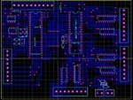
I did not produce any schematic, but you can find PCB view attached.
Untitled.jpg
 

Status
Not open for further replies.

Similar threads

Part and Inventory Search

Welcome to EDABoard.com

Sponsor

Back
Top