Continue to Site

Welcome to EDAboard.com

Welcome to our site! EDAboard.com is an international Electronics Discussion Forum focused on EDA software, circuits, schematics, books, theory, papers, asic, pld, 8051, DSP, Network, RF, Analog Design, PCB, Service Manuals... and a whole lot more! To participate you need to register. Registration is free. Click here to register now.

[SOLVED] PIC16F76 and LCD in CCS not run in ISIS Proteus

Status
Not open for further replies.

nagkiller

Full Member level 4
Joined
Jul 9, 2009
Messages
238
Helped
37
Reputation
74
Reaction score
37
Trophy points
1,308
Location
Brazil
Activity points
2,703
Hello!!!

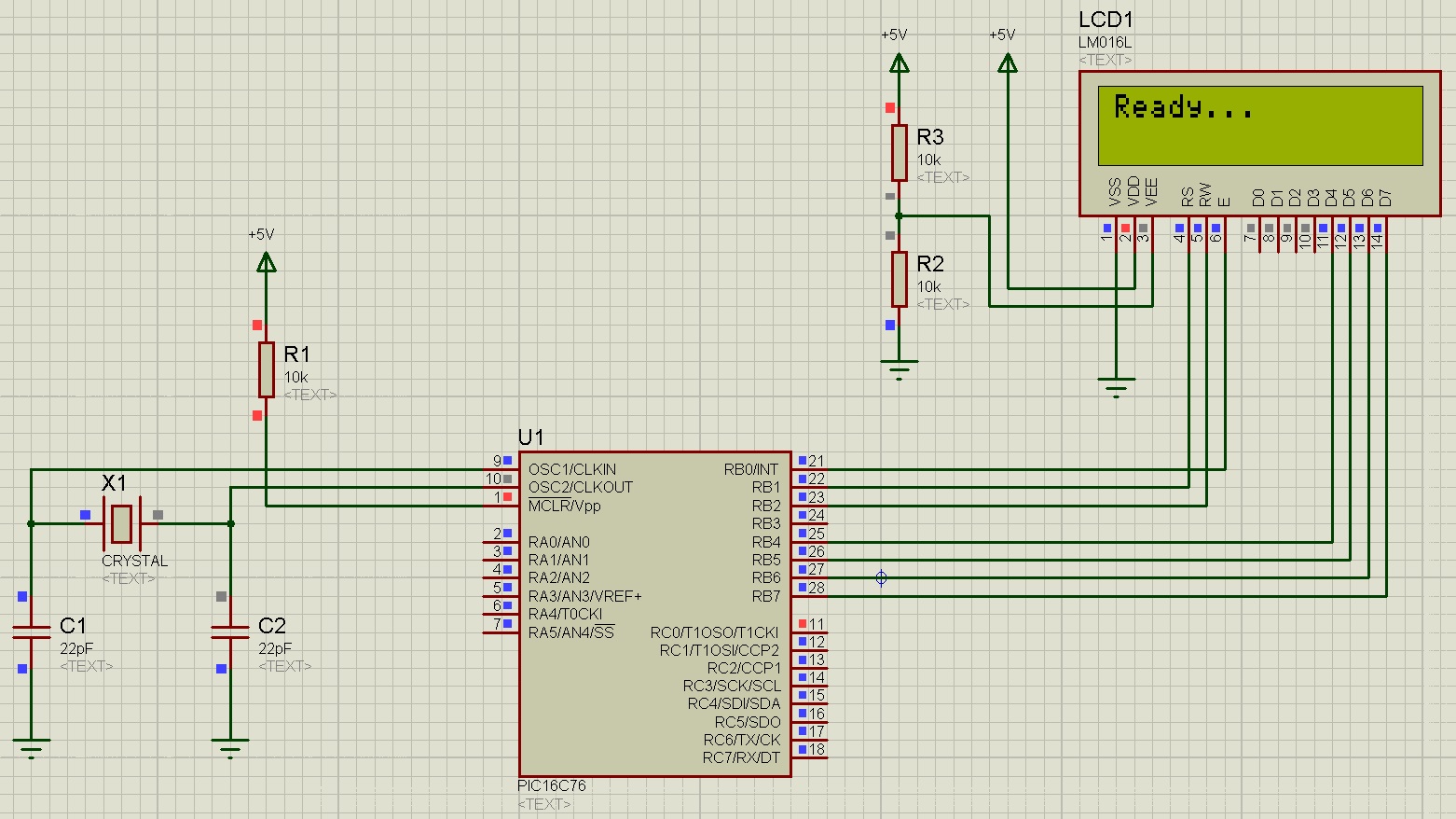
I need help in CCS compiler (V4.140), the PIC16F76 cannot run lcd in ISIS PROTEUS (V7.10)...

I trying the example created by the Project Wizard.

This is the log

"
Message Source Time
ISIS Release 7.10.00 (Build 12325) (C) Labcenter Electronics 1990- 2011.
Source code build completed OK.
Compiling design 'C:\Program Files\PICC\Projetos\PIC16F76\Outro\Teste LCD.DSN'.
Netlist compilation completed OK.
Netlist linking completed OK.
Partition analysis completed OK.
Simulating partition [77F7A989]
PROSPICE 7.10.00 (Build 11592) (C) Labcenter Electronics 1993-2011.
Loaded netlist 'C:\Users\xxxxx\AppData\Local\Temp\LISA0013.SDF' for design 'C:\Program Files\PICC\Projetos\PIC16F76\Outro\Teste LCD.DSN'
PIC16 model release 7.10.00 (Build 12500) simulating PIC1676 device. U1
[COFF] Loading PIC COFF file 'Outro.COF'. U1
END Of BOOTING U1
Loaded 356 program words and 0 data bytes. U1
Logic contention(s) detected on net #00003.
Logic contention(s) detected on net #00002.
Logic contention(s) detected on net #00001.
[PIC16 MEMORY] PC=0x015F. Attempt to write unimplemented memory location 0x010D with 0x0C ignored. U1
[PIC16 MEMORY] PC=0x0161. Attempt to write unimplemented memory location 0x010F with 0x00 ignored. U1
[PIC16 MEMORY] PC=0x00F5. Attempt to read unimplemented memory location 0x018C ignored. U1
[PIC16 MEMORY] PC=0x00F5. Attempt to write unimplemented memory location 0x018C with 0x80 ignored. U1
[PIC16 MEMORY] PC=0x00F6. Attempt to read unimplemented memory location 0x018C ignored. U1
[PIC16 MEMORY] PC=0x00F6. Attempt to write unimplemented memory location 0x018C with 0x01 ignored. U1
[PIC16 MEMORY] PC=0x00FA. Attempt to read unimplemented memory location 0x010C ignored. U1

"

Thanks.

Sorry for bad english.
 

Attachments

  • Outro.zip
    23.9 KB · Views: 145

These three

Logic contention(s) detected on net #00003.
Logic contention(s) detected on net #00002.
Logic contention(s) detected on net #00001.

shows that some LCD pins are not properly initialized with TRISx. The pins should be configured as output pins. Post your code so that it can be checked.
 

There is all on the zip attached!!!

"
Code:
#include <16F76.h>
#device adc=8

#FUSES NOWDT                    //No Watch Dog Timer
#FUSES HS                       //High speed Osc (> 4mhz for PCM/PCH) (>10mhz for PCD)
//#FUSES XT                       //Crystal osc <= 4mhz for PCM/PCH , 3mhz to 10 mhz for PCD
#FUSES NOBROWNOUT               //No brownout reset

#use delay(clock=16000000)

#define RS_PIN       B5
#define RW_PIN       B6
#define ENABLE_PIN   B7
#define Data4        C0
#define Data5        C1
#define Data6        C2
#define Data7        C3

#define LED_OSC      PIN_A5

#include <lcd.c>
void main()
{
   //set_tris_a(0x00);
   //set_tris_b(0x00);
   //set_tris_c(0x00);
   //OUTPUT_A(0b00000001);
   //OUTPUT_B(0);
   //OUTPUT_C(0);
   lcd_init();
   lcd_putc("\fReady...\n");
   while(TRUE)
   {
      OUTPUT_TOGGLE(LED_OSC);
      delay_ms(1000);
   }
}
"

In real circuit of LCD, the pins D0-D3 is connected to GND(0V)!!!

Thanks for support!!!
 
Last edited:

Why tris code is disabled (commented) in code? I don't know CCS C but you have to make pins B5, B6, B7, C0, C1, C2, C3 as output pins. Just make PORTB and PORTC as output ports.
 

My problem is the memory error!!!

Outputs or inputs works...

I replace code for

Code:
#use FIXED_IO( A_outputs=PIN_A5)
#use FIXED_IO( B_outputs=PIN_B5,PIN_B6,PIN_B7 )
#use FIXED_IO( C_outputs=PIN_C0,PIN_C1,PIN_C2,PIN_C3 )

But LCD not show the message... not initialize... Show error in memory...

Thanks

PS: If I use Hitech C(V9.83) , works fine in isis proteus, and without error!!!
 
Last edited:

Zip and post your proteus file, hex file, cof file, and if possible c code.

Edit: Unless the logic contentions are solved your simulation will not work. Please post lcd.c file.

You are getting those memory errors because pins C0, C1, and C2 have logic contentions that is it is configured as both input and output and when it is like input data is written to the pins.

Try this lcd_putc(X);

The function expects a character and not string.
 
Last edited:

This is all package.

Include the ccs LCD.C.

This is a example called EX_LCDKB.C by CCS
Code:
/////////////////////////////////////////////////////////////////////////
////                           EX_LCDKB.C                            ////
////                                                                 ////
////  This program uses both the KBD.C and LCD.C drivers to allow    ////
////  keypad entry and LCD display.  All keys are echoed except *    ////
////  that will clear the display.  Either the kbd_getc or lcd_putc  ////
////  may be replaced with getc or putc to use just one device with  ////
////  the RS-232.                                                    ////
////                                                                 ////
////  Configure the CCS prototype card as follows:                   ////
////     Plug in both the LCD and KEYPAD.                            ////
////                                                                 ////
////  This example will work with the PCB, PCM and PCH compilers.    ////
////  The following conditional compilation lines are used to        ////
////  include a valid device for each compiler.  Change the device,  ////
////  clock and RS232 pins for your hardware if needed.              ////
/////////////////////////////////////////////////////////////////////////
////        (C) Copyright 1996,2003 Custom Computer Services         ////
//// This source code may only be used by licensed users of the CCS  ////
//// C compiler.  This source code may only be distributed to other  ////
//// licensed users of the CCS C compiler.  No other use,            ////
//// reproduction or distribution is permitted without written       ////
//// permission.  Derivative programs created using this software    ////
//// in object code form are not restricted in any way.              ////
/////////////////////////////////////////////////////////////////////////


#if defined(__PCB__)
#include <16C56.h>
#fuses HS,NOWDT,NOPROTECT
#use delay(clock=20000000)

#elif defined(__PCM__)
#include <16F877.h>
#fuses HS,NOWDT,NOPROTECT,NOLVP
#use delay(clock=20000000)

#elif defined(__PCH__)
#include <18F452.h>
#fuses HS,NOWDT,NOPROTECT,NOLVP
#use delay(clock=20000000)
#endif

#include <lcd.c>
#include <kbd.c>


void main() {
   char k;

   lcd_init();
   kbd_init();

   lcd_putc("\fReady...\n");

   while (TRUE) {
      k=kbd_getc();
      if(k!=0)
        if(k=='*')
          lcd_putc('\f');
        else
          lcd_putc(k);
   }
}

Thanks.
 

Attachments

  • Outro (All pack).zip
    2.5 MB · Views: 130

See the image
 

Attachments

  • lcd.jpg
    lcd.jpg
    401.7 KB · Views: 230
lcd_putc(X); not work!!!
Unknow identfier!!!
I try lcd_putc(0x35); too...
Or not show if I use lcd_putc("X");

The memory is solved replacing the PIC16F76 on c code to PIC16C76!!!

But not work.

How much Its hard to use PIC16F76 with LCD in CCS!!!

Thanks.

- - - Updated - - -

Work in Wrong Mode!!!!
Code:
#include <16C76.h>
#device adc=8

#FUSES NOWDT 
#FUSES XT
#FUSES NOBROWNOUT
#FUSES PROTECT

#use delay(clock=16000000)

[B]#define RS_PIN C0
#define RW_PIN C1
#define ENABLE_PIN C2[/B]
#define Data4 B4
#define Data5 B5
#define Data6 B6
#define Data7 B7

#include <lcd.c>

void main()
{
   set_tris_a(0);
   set_tris_b(0);
   set_tris_c(0);
   
   lcd_init();
   lcd_putc("\fReady...\n");

   while(TRUE)
   {


   }

}

But The LCD PINS in ISIS is:

ENABLE = RB0;
RS = RB1
RW = RB2

D4 = RB4
D5 = RB5
D6 = RB6
D7 = RB7


It is a joke!!!

Thanks.
 
Last edited:

insert a delay_ms(16); after the lcd_init command so that the lcd has time to initialize......
 

I inserted a delay_ms(xx); after lcd_init(); but in the first schematic not works!!!

RB5 = RS
RB6 = RW
RB7 = ENEBLE
RC0 = D4
RC1 = D5
RC2 = D6
RC3 = D7

Works if I change schematic like follow:

ENABLE = RB0;
RS = RB1
RW = RB2

D4 = RB4
D5 = RB5
D6 = RB6
D7 = RB7

Thanks

- - - Updated - - -

My second changes is insert #define LCD_DATA_PORT getenv("SFR:PORTC") into main.c code. And its works too!!!

"
Code:
#include <16C76.h>
#device adc=8

#FUSES NOWDT                    //No Watch Dog Timer
#FUSES HS                       //High speed Osc (> 4mhz for PCM/PCH) (>10mhz for PCD)
#FUSES NOBROWNOUT               //No brownout reset

#use delay(clock=16000000)

#define LCD_DATA_PORT getenv("SFR:PORTC")

#define RS_PIN       C1
#define RW_PIN       C2
#define ENABLE_PIN   C0
#define Data4        C4
#define Data5        C5
#define Data6        C6
#define Data7        C7

#define LED_OSC      PIN_A5

#include <lcd.c>
void main()
{
   set_tris_a(0x00);
   set_tris_b(0x00);
   set_tris_c(0x00);
   OUTPUT_A(0b00000001);
   OUTPUT_B(0);
   OUTPUT_C(0);
   lcd_init();   
   lcd_putc("\fReady...\n");
   while(TRUE)
   {
      OUTPUT_TOGGLE(LED_OSC);
      delay_ms(100);
   }
}
"
And change all pins of lcd to PORTC.

Thanks for all support!!!
 

#define LCD_DATA_PORT getenv("SFR:pORTC") is for PORT setting and the other method is for individual pin setting. You have to use any one method i.e., either PORT or pin.
 

I made a temperature sensor using led.....check if this could help u....


#include "C:\Documents and Settings\User\Desktop\E.thermometer\ADC Calibrator 16f877a\main.h"

#define LCD_ENABLE_PIN PIN_C3
#define LCD_RS_PIN PIN_C1
#define LCD_RW_PIN PIN_C2
#define LCD_DATA4 PIN_c4
#define LCD_DATA5 PIN_c5
#define LCD_DATA6 PIN_c6
#define LCD_DATA7 PIN_c7
#define LCD_TYPE 2
#include <lcd.c>

void main()
{
setup_adc_ports(ALL_ANALOG);
setup_adc(ADC_CLOCK_DIV_2);
setup_psp(PSP_DISABLED);
setup_spi(SPI_SS_DISABLED);
setup_timer_0(RTCC_INTERNAL|RTCC_DIV_1);
setup_timer_1(T1_DISABLED);
setup_timer_2(T2_DISABLED,0,1);
setup_comparator(NC_NC_NC_NC);
setup_vref(FALSE);

lcd_init();
delay_ms(20);
int16 digital_reading; // ADC resolution is 10Bit, an 8Bit integer is not enough to hold the reading
float temp;

set_adc_channel(0);
delay_ms(1);

printf(lcd_putc,"Digital");
printf(lcd_putc,"\nThermometer V1.0");
DELAY_MS(1000);
printf(lcd_putc,"\fBy");
printf(lcd_putc,"\nALKESHWR");
DELAY_MS(1000);

while(1) // infinite loop
{
printf(lcd_putc,"\fTemperature is:");
digital_reading = read_adc(); // capture current temperature reading
delay_us(100); // 0.1ms delay for ADC stabilization
temp = digital_reading * 0.4883; // convert reading to Celsius
lcd_gotoxy(1,2); // point LCD cursor to col1 row2
printf(lcd_putc,"%2.1f'C.",temp); // print value on LCD

delay_ms(1000); // 1 second delay between readings

printf(lcd_putc,"\fTemperature is:");
digital_reading = read_adc(); // capture current temperature reading
delay_us(100); // 0.1ms delay for ADC stabilization
temp = digital_reading * 0.4883; // convert reading to Celsius
lcd_gotoxy(1,2); // point LCD cursor to col1 row2
printf(lcd_putc,"%2.1f'C..",temp); // print value on LCD

delay_ms(1000); // 1 second delay between readings

printf(lcd_putc,"\fTemperature is:");
digital_reading = read_adc(); // capture current temperature reading
delay_us(100); // 0.1ms delay for ADC stabilization
temp = digital_reading * 0.4883; // convert reading to Celsius
lcd_gotoxy(1,2); // point LCD cursor to col1 row2
printf(lcd_putc,"%2.1f'C...",temp); // print value on LCD

delay_ms(1000); // 1 second delay between readings

printf(lcd_putc,"\fTemperature is:");
digital_reading = read_adc(); // capture current temperature reading
delay_us(100); // 0.1ms delay for ADC stabilization
temp = digital_reading * 0.4883; // convert reading to Celsius
lcd_gotoxy(1,2); // point LCD cursor to col1 row2
printf(lcd_putc,"%2.1f'C....",temp); // print value on LCD

delay_ms(1000); // 1 second delay between readings
}
}
 
My solution is use flex_lcd.c!!!

Works fine with PIC16C76 and Display LCD.
Main c:
Code:
#include <16C76.h>
#device adc=8

#FUSES NOWDT                    //No Watch Dog Timer
#FUSES HS                       //High speed Osc (> 4mhz for PCM/PCH) (>10mhz for PCD)
//#FUSES XT                       //Crystal osc <= 4mhz for PCM/PCH , 3mhz to 10 mhz for PCD
#FUSES NOBROWNOUT               //No brownout reset

#use delay(clock=16000000)

#define LED_OSC      PIN_A5

#include "flex_lcd.c"
void main()
{
   set_tris_a(0x00);
   set_tris_b(0x00);
   set_tris_c(0x00);
   OUTPUT_A(0);
   OUTPUT_B(0);
   OUTPUT_C(0);
   lcd_init();
   lcd_putc("\fReady...\n");
   while(TRUE)
   {
      OUTPUT_TOGGLE(LED_OSC);
      delay_ms(10);
   }
}

flex_lcd.c:
Code:
// flex_lcd.c 
 
 // These pins are for the Microchip PicDem2-Plus board, 
 // which is what I used to test the driver.  Change these 
 // pins to fit your own board. 
 
 #define LCD_DB4   PIN_C0 
 #define LCD_DB5   PIN_C1 
 #define LCD_DB6   PIN_C2 
 #define LCD_DB7   PIN_C3 
 
 #define LCD_E     PIN_B7 
 #define LCD_RS    PIN_B5 
 #define LCD_RW    PIN_B6 
 
 // If you only want a 6-pin interface to your LCD, then 
 // connect the R/W pin on the LCD to ground, and comment 
 // out the following line. 
 
// #define USE_LCD_RW   1      
 
 //======================================== 
 
 #define lcd_type 2        // 0=5x7, 1=5x10, 2=2 lines 
 #define lcd_line_two 0x40 // LCD RAM address for the 2nd line 
 
 
 int8 const LCD_INIT_STRING[4] = 
 { 
  0x20 | (lcd_type << 2), // Func set: 4-bit, 2 lines, 5x8 dots 
  0xc,                    // Display on 
  1,                      // Clear display 
  6                       // Increment cursor 
  }; 
                               
 
 //------------------------------------- 
 void lcd_send_nibble(int8 nibble) 
 { 
 // Note:  !! converts an integer expression 
 // to a boolean (1 or 0). 
  output_bit(LCD_DB4, !!(nibble & 1)); 
  output_bit(LCD_DB5, !!(nibble & 2));  
  output_bit(LCD_DB6, !!(nibble & 4));    
  output_bit(LCD_DB7, !!(nibble & 8));    
 
  delay_cycles(1); 
  output_high(LCD_E); 
  delay_us(2); 
  output_low(LCD_E); 
 } 
 
 //----------------------------------- 
 // This sub-routine is only called by lcd_read_byte(). 
 // It's not a stand-alone routine.  For example, the 
 // R/W signal is set high by lcd_read_byte() before 
 // this routine is called.      
 
 #ifdef USE_LCD_RW 
 int8 lcd_read_nibble(void) 
 { 
 int8 retval; 
 // Create bit variables so that we can easily set 
 // individual bits in the retval variable. 
 #bit retval_0 = retval.0 
 #bit retval_1 = retval.1 
 #bit retval_2 = retval.2 
 #bit retval_3 = retval.3 
 
 retval = 0; 
     
 output_high(LCD_E); 
 delay_cycles(1); 
 
 retval_0 = input(LCD_DB4); 
 retval_1 = input(LCD_DB5); 
 retval_2 = input(LCD_DB6); 
 retval_3 = input(LCD_DB7); 
   
 output_low(LCD_E); 
     
 return(retval);    
 }    
 #endif 
 
 //--------------------------------------- 
 // Read a byte from the LCD and return it. 
 
 #ifdef USE_LCD_RW 
 int8 lcd_read_byte(void) 
 { 
 int8 low; 
 int8 high; 
 
 output_high(LCD_RW); 
 delay_cycles(1); 
 
 high = lcd_read_nibble(); 
 
 low = lcd_read_nibble(); 
 
 return( (high<<4) | low); 
 } 
 #endif 
 
 //---------------------------------------- 
 // Send a byte to the LCD. 
 void lcd_send_byte(int8 address, int8 n) 
 { 
 output_low(LCD_RS); 
 
 #ifdef USE_LCD_RW 
 while(bit_test(lcd_read_byte(),7)) ; 
 #else 
 delay_us(60);  
 #endif 
 
 if(address) 
    output_high(LCD_RS); 
 else 
    output_low(LCD_RS); 
       
  delay_cycles(1); 
 
 #ifdef USE_LCD_RW 
 output_low(LCD_RW); 
 delay_cycles(1); 
 #endif 
 
 output_low(LCD_E); 
 
 lcd_send_nibble(n >> 4); 
 lcd_send_nibble(n & 0xf); 
 } 
 
 //---------------------------- 
 void lcd_init(void) 
 { 
 int8 i; 
 
 output_low(LCD_RS); 
 
 #ifdef USE_LCD_RW 
 output_low(LCD_RW); 
 #endif 
 
 output_low(LCD_E); 
 
 delay_ms(15); 
 
 for(i=0 ;i < 3; i++) 
    { 
     lcd_send_nibble(0x03); 
     delay_ms(5); 
    } 
 
 lcd_send_nibble(0x02); 
 
 for(i=0; i < sizeof(LCD_INIT_STRING); i++) 
    { 
     lcd_send_byte(0, LCD_INIT_STRING[i]); 
     
     // If the R/W signal is not used, then 
     // the busy bit can't be polled.  One of 
     // the init commands takes longer than 
     // the hard-coded delay of 60 us, so in 
     // that case, lets just do a 5 ms delay 
     // after all four of them. 
     #ifndef USE_LCD_RW 
     delay_ms(5); 
     #endif 
    } 
 
 } 
 
 //---------------------------- 
 
 void lcd_gotoxy(int8 x, int8 y) 
 { 
 int8 address; 
 
 if(y != 1) 
    address = lcd_line_two; 
 else 
    address=0; 
 
 address += x-1; 
 lcd_send_byte(0, 0x80 | address); 
 } 
 
 //----------------------------- 
 void lcd_putc(char c) 
 { 
  switch(c) 
    { 
     case '\f': 
       lcd_send_byte(0,1); 
       delay_ms(2); 
       break; 
     
     case '\n': 
        lcd_gotoxy(1,2); 
        break; 
     
     case '\b': 
        lcd_send_byte(0,0x10); 
        break; 
     
     default: 
        lcd_send_byte(1,c); 
        break; 
    } 
 } 
 
 //------------------------------ 
 #ifdef USE_LCD_RW 
 char lcd_getc(int8 x, int8 y) 
 { 
 char value; 
 
 lcd_gotoxy(x,y); 
 
 // Wait until busy flag is low. 
 while(bit_test(lcd_read_byte(),7));  
 
 output_high(LCD_RS); 
 value = lcd_read_byte(); 
 output_low(lcd_RS); 
 
 return(value); 
 } 
 #endif

Thanks for ALL!!!!
 

My error is in the #defines!!!
Code:
#define LCD_ENABLE_PIN  PIN_B7
#define LCD_RS_PIN      PIN_B5
#define LCD_RW_PIN      PIN_B6
#define LCD_DATA4       PIN_C0
#define LCD_DATA5       PIN_C1
#define LCD_DATA6       PIN_C2
#define LCD_DATA7       PIN_C3

This is full code using driver lcd.c included into CCS installation.

Code:
#include <16C76.h>
#device adc=8

#FUSES NOWDT
#FUSES XT
#FUSES NOBROWNOUT

#use delay(clock=4000000)

#define LCD_ENABLE_PIN  PIN_B7
#define LCD_RS_PIN      PIN_B5
#define LCD_RW_PIN      PIN_B6
#define LCD_DATA4       PIN_C0
#define LCD_DATA5       PIN_C1
#define LCD_DATA6       PIN_C2
#define LCD_DATA7       PIN_C3
#include <lcd.c>

void main()
{
   lcd_init();
   delay_ms(10);
   lcd_putc("\fDISPLAY TEST LINE 1");
   lcd_putc("\nDISPLAY TEST LINE 2");
   while(TRUE)
   {
        output_toggle(PIN_B0);
        delay_ms(500);      
   }
}
 

These three

Logic contention(s) detected on net #00003.
Logic contention(s) detected on net #00002.
Logic contention(s) detected on net #00001.

shows that some LCD pins are not properly initialized with TRISx. The pins should be configured as output pins. Post your code so that it can be checked.

THX it really worked
 

Status
Not open for further replies.

Similar threads

Part and Inventory Search

Welcome to EDABoard.com

Sponsor

Back
Top