Continue to Site

Welcome to EDAboard.com

Welcome to our site! EDAboard.com is an international Electronics Discussion Forum focused on EDA software, circuits, schematics, books, theory, papers, asic, pld, 8051, DSP, Network, RF, Analog Design, PCB, Service Manuals... and a whole lot more! To participate you need to register. Registration is free. Click here to register now.

PIC10F220 RC filter first order by numerical simulation in the microcontroller

Status
Not open for further replies.
SO or?
I no longer see the' #' HERE on my page

Code:
[COLOR="#0000FF"] #define[/COLOR]	 Clock	    GPIO,1	; Associates the name "Clock" on GP1 output
 [COLOR="#0000FF"]   #define [/COLOR]  D_DATA	    GPIO,2	;Associates the name"donne_DATA	" on GP2 input
;************************************************************************
[COLOR="#FF0000"]  STROBE MACRO[/COLOR]
   [COLOR="#0000FF"] bsf[/COLOR] CLK
  [COLOR="#0000FF"]  call [/COLOR]Delay500us
   [COLOR="#0000FF"] bcf[/COLOR] CLK
[COLOR="#FF0000"] ENDM[/COLOR]

[COLOR="#FF0000"] EStrobe MACRO [/COLOR]        
    [COLOR="#0000FF"]bsf [/COLOR]D_DATA
	[COLOR="#0000FF"]call[/COLOR] Delay500us
  [COLOR="#0000FF"]  bcf [/COLOR]D_DATA
;*********************************************************  
[COLOR="#FF0000"]LCDUpdate[/COLOR]

[COLOR="#0000FF"]movlw[/COLOR] 8				
	[COLOR="#0000FF"]movwf[/COLOR] Counter
[COLOR="#FF0000"]SerialLoop[/COLOR]
	[COLOR="#0000FF"]rrf[/COLOR] LCD_Data,f		
	[COLOR="#0000FF"]btfss[/COLOR] STATUS,C		
[COLOR="#0000FF"]	goto [/COLOR]SendLow
	[COLOR="#0000FF"]bsf[/COLOR] D_Data			
	[COLOR="#0000FF"]goto[/COLOR] SendClock
[COLOR="#FF0000"]SendLow[/COLOR]
	[COLOR="#0000FF"]bcf [/COLOR]D_Data			
[COLOR="#FF0000"]SendClock[/COLOR]
	[COLOR="#0000FF"]bcf[/COLOR] Clock			
	[COLOR="#0000FF"]bsf[/COLOR] Clock			
	[COLOR="#0000FF"]decfsz[/COLOR] Counter,f	
	[COLOR="#0000FF"]goto [/COLOR]SerialLoop
 
Last edited by a moderator:
SO or?
I no longer see the' #' HERE on my page

Code:
[COLOR="#0000FF"] #define[/COLOR]	 Clock	    GPIO,1	; Associates the name "Clock" on GP1 output
 [COLOR="#0000FF"]   #define [/COLOR]  D_DATA	    GPIO,2	;Associates the name"donne_DATA	" on GP2 input
;************************************************************************
[COLOR="#FF0000"]  STROBE MACRO[/COLOR]
   [COLOR="#0000FF"] bsf[/COLOR] CLK
  [COLOR="#0000FF"]  call [/COLOR]Delay500us
   [COLOR="#0000FF"] bcf[/COLOR] CLK
[COLOR="#FF0000"] ENDM[/COLOR]

[COLOR="#FF0000"] EStrobe MACRO [/COLOR]        
    [COLOR="#0000FF"]bsf [/COLOR]D_DATA
	[COLOR="#0000FF"]call[/COLOR] Delay500us
  [COLOR="#0000FF"]  bcf [/COLOR]D_DATA
;*********************************************************  
[COLOR="#FF0000"]LCDUpdate[/COLOR]

[COLOR="#0000FF"]movlw[/COLOR] 8				
	[COLOR="#0000FF"]movwf[/COLOR] Counter
[COLOR="#FF0000"]SerialLoop[/COLOR]
	[COLOR="#0000FF"]rrf[/COLOR] LCD_Data,f		
	[COLOR="#0000FF"]btfss[/COLOR] STATUS,C		
[COLOR="#0000FF"]	goto [/COLOR]SendLow
	[COLOR="#0000FF"]bsf[/COLOR] D_Data			
	[COLOR="#0000FF"]goto[/COLOR] SendClock
[COLOR="#FF0000"]SendLow[/COLOR]
	[COLOR="#0000FF"]bcf [/COLOR]D_Data			
[COLOR="#FF0000"]SendClock[/COLOR]
	[COLOR="#0000FF"]bcf[/COLOR] Clock			
	[COLOR="#0000FF"]bsf[/COLOR] Clock			
	[COLOR="#0000FF"]decfsz[/COLOR] Counter,f	
	[COLOR="#0000FF"]goto [/COLOR]SerialLoop

I have done right?

- - - Updated - - -

please If it's just how I am introduced or call later in my program
 

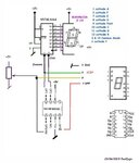
what hardware are you using ?
LCD + 74164 or 74595 ? , 7 segment led display + 74XXXX ?
or other ?

you define MACRO to simply the writing of code, so use it ..
Code:
.....


LCDUpdate                  ; entry of the subroutine
        movlw 8                
    movwf Counter
SerialLoop
    rrf LCD_Data,f        
    btfss STATUS,C        
    goto SendLow
    bsf D_Data            
    goto SendClock
SendLow
    bcf D_Data            
SendClock
    STROBE            
    decfsz Counter,f    
    goto SerialLoop
        return                   ; <- return  to main program


      and use it as subroutine
       in the main loop program


       movf Beaufort,W     ; your value to display  0<= value <=9
       addlw 0x30;          // or Addlw '0' to transform in ascii '0' to '9'
       movwf LCDData
       call LCDUpdate


nota : i suppose the software is adapted to your hardware .. not sure !


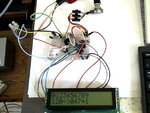
Display on LCD + 74HC164, uses 2 wires
MPLAB ASM PIC12F683 .. for real test .. Ok
View attachment 12F683_LCD_2w_74164.zip

running:
1rst line .. just display values from 0 to 9
2nd line : incremental counter value from 0 to 255
then ADC value 0 to 255
then Beaufort value 0 to 9
refresh every 1 seconde using timer0
all delay made by timer0.


Pic12F683_LCD_76164_2w_asm.jpg
 

paulfjujo, it has to be an LCD and 10F220 which only has 6 pins in total! VSS,VDD, one digital input, one analog input and two bidirectional I/O.

Thierry has so far proved they can copy and paste but made no effort to do any coding or decide on the type of interface the want to use.

Brian.
 

Status
Not open for further replies.

Similar threads

Part and Inventory Search

Welcome to EDABoard.com

Sponsor

Back
Top