Continue to Site

Welcome to EDAboard.com

Welcome to our site! EDAboard.com is an international Electronics Discussion Forum focused on EDA software, circuits, schematics, books, theory, papers, asic, pld, 8051, DSP, Network, RF, Analog Design, PCB, Service Manuals... and a whole lot more! To participate you need to register. Registration is free. Click here to register now.

PIC10F220 RC filter first order by numerical simulation in the microcontroller

Status
Not open for further replies.
He will be using the circuit mentioned in post #38.
 

SPI (SPI data and clk SPI) SPI standard with a line for the clk and a line for datas (so two I/O)
is that correct? only (SPI data and clk SPI)

Code:
SPI_IN_OUT
          movf    DATA_OUT,w    ; get datum for transmission
          movwf   SSPBUF             ;put into SSPBUF
 SS_IN_OUT_LOOP
          btfss   SSPCON,WCOL   ; dit it make it ?
          goto    SPI_IN_OUT_CONT ;  if so THEN continue
          bcf     SSPCON,WCOL           ;Else reset WCOL and try again
          goto    SSP_IN_OUT_LOOP
SPI_IN_OUT_CONT
          bsf   STATUS ,RPO   ; Change to Bank0
          btfss  SSPSTAT ,BF    ;  check for buffer full
          goto   SPI_IN_OUT_CONT ;  if not then poll again
          bcf   STATUS ,RPO   ; Back to Bank1
          movf   SSPBUF ,w         ; else get the received datum
          movwf    DATA_IN         ; put away
          return
 

Does your PIC have Hardware SPI ? I don't know. If you use the circuit mentioned in post #38 then you are sending data serially. It is not SPI. It is different from SPI. Only if your PIC has hardware SPI there will be SSPBUF and other registers associated with SPI.
 

SPI (SPI data and clk SPI) SPI standard with a line for the clk and a line for datas (so two I/O)
is that correct? only (SPI data and clk SPI)

Code:
SPI_IN_OUT
          movf    DATA_OUT,w    ; get datum for transmission
          movwf   SSPBUF             ;put into SSPBUF
 SS_IN_OUT_LOOP
          btfss   SSPCON,WCOL   ; dit it make it ?
          goto    SPI_IN_OUT_CONT ;  if so THEN continue
          bcf     SSPCON,WCOL           ;Else reset WCOL and try again
          goto    SSP_IN_OUT_LOOP
SPI_IN_OUT_CONT
          bsf   STATUS ,RPO   ; Change to Bank0
          btfss  SSPSTAT ,BF    ;  check for buffer full
          goto   SPI_IN_OUT_CONT ;  if not then poll again
          bcf   STATUS ,RPO   ; Back to Bank1
          movf   SSPBUF ,w         ; else get the received datum
          movwf    DATA_IN         ; put away
          return

So one LCD driven by SPI. that's what I'd like to code

- - - Updated - - -

Does your PIC have Hardware SPI ? I don't know. If you use the circuit mentioned in post #38 then you are sending data serially. It is not SPI. It is different from SPI. Only if your PIC has hardware SPI there will be SSPBUF and other registers associated with SPI.

My Pic has no Hardware SPI I have to code a SPI software only Interface to the LCD module, one LCD driven by SPI
only Interface to the LCD module -->(SPI data and clk SPI)
 

So one LCD driven by SPI. that's what I'd like to code

- - - Updated - - -


My Pic has no Hardware SPI I have to code a SPI software only Interface to the LCD module, one LCD driven by SPI
only Interface to the LCD module -->(SPI data and clk SPI)

the aim is to make a filter with a cutoff frequency that depends on my averaging time, and takes the analog voltage in input (so use an ADC)
Then take the output of this filter and send it to SPI. which means Only Interface to the LCD module: SPI (SPI data and SPI clk) -- (LCD driven by SPI)
 

If you want to use SPI for LCD then you have to mention what SPI port expander you will use between PIC and LCD. Will you use MCP23S09 8 bit port expander between PIC and LCD. If you can use MCP23S09 then I will try to port my C code to asm.
 

I repeat you CAN NOT use SPI.

SPI requires THREE connections - you only have two.

milan.rajik, please look at the data sheet for this PIC. It is one of the baseline processors, available in 6 or 8 pin (with 2 pins unused!) packages , only 256 bytes of program memory and 16 bytes of RAM. It has no internal peripherals except one 8-bit timer and an 8-bit ADC. Most importantly here, it only has three IO pins and one input pin. One of the IO pins has to be used as the analog input.

Brian.
 
@betwixt

I am talking about soft SPI. I recently did a MCP23S09 based SPI LCD code in C. It uses only one function that is SPI_Write(). SPI_Write() sends out data MSB first serially. It used 3 pins CS, CLK, DATA. I think we can leave out CS pin and use software SPI with MCP23S09. We don't have to control the CS line. We can make CS pin low all the time so that it accepts whatever data is sent to it. So, we need only CLK and DATA. I think it will work. All that is needed is a SPI_Write function in asm which sends data serially and MSB first.
 

If you want to use SPI for LCD then you have to mention what SPI port expander you will use between PIC and LCD. Will you use MCP23S09 8 bit port expander between PIC and LCD. If you can use MCP23S09 then I will try to port my C code to asm.

just program a SPI (SPIdatas and SPI clk), So a Serial Peripheral Interface SPI (just do a software SPI)
There are yet no LCD,no HD44780U, or MCP23S09 ,nothing was done connection ,I have just preconfigure the program with a Serial Peripheral Interface SPI

he just was written (Interface to the LCD module: SPI (SPI data and SPI clk)) , SPI standard with a line for the clk and a line for datas (so two I/O)
We have not received LCD, no scheme no HD44780U, not MCP23S09 nothing we just need to make a program with an interface to the LCD module (SPI (SPI data and SPI clk))

I do not know if anyone understands me; because I'm already sick with this theme, and the teacher does not respond to the written questions , he said, just to do what was written in the book of specifications
 

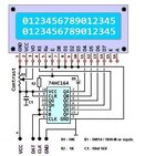
you can have a look on this 2 wires LCD interface in ASM use a 74HTC164 + classic LCD

2-wire LCD 74LS164-1b.JPG

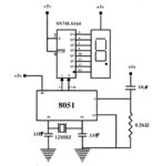
or a better solution adapted to your case.. with only one 7seg digit and 2 wires to drive it
with your Own MCU..
hardware_8051_1x7segment_serial_sch.GIF
 

or a better solution adapted to your case.. with only one 7seg digit and 2 wires to drive it
with your Own MCU..
View attachment 118667[/QUOTE]


and how can we encode this one ?
that is a better solution
 

I repeat you CAN NOT use SPI.

SPI requires THREE connections - you only have two.

milan.rajik, please look at the data sheet for this PIC. It is one of the baseline processors, available in 6 or 8 pin (with 2 pins unused!) packages , only 256 bytes of program memory and 16 bytes of RAM. It has no internal peripherals except one 8-bit timer and an 8-bit ADC. Most importantly here, it only has three IO pins and one input pin. One of the IO pins has to be used as the analog input.

Brian.
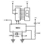
betwixt Can we use an SPI with this scheme?
hardware_8051_1x7segment_serial_sch.GIF
 

It can be done with a CD4094, 75LS595, 75HC164 or any other shift register but it will not work with SPI. if you put SPI in permanent 'enabled' state it will never latch the serial bits to the parallel output pins. If you use the LED examples in the previous posts, it will not work with LCD and random segments will appear during the bit shifting.

I do not know if anyone understands me; because I'm already sick with this theme, and the teacher does not respond to the written questions , he said, just to do what was written in the book of specifications

I understand your frustration but you have given us very little information to work from and been indecisive about the type of display you intend to use. You started with a parallel LCD, then wanted SPI LCD and your latest post is showing a (bad) design for LED. I think this is supposed to be an exercise in learning how to overcome a simple task when you have limited resources but you seem to be pushing us to do the work for you instead of trying to understand the options available to you. Edaboard is not a free "do your homework for you" service, all of us are volunteers who give our time freely to help you but we try to teach and guide you so you can solve problems yourself.

Brian.
 
MCP23S09 cannot be used. It needs a CS line. I tried without CS line and it doesn't work. There should be a start condition before sending the command word to MCP23S09 and then address of the register to which data has to be written must be sent and then actual data has to be sent. If there is not start and stop conditions then command word sent after writing to say IODIR will be considered as a new data for IODIR and it will not write it to the next register. So, you cannot use any SPI device for LCD as SPI device like MCP23S09 will require 3 lines namely CS, CLK, DATA. So, you have to use 2 wire serial interface mentioned earlier or you have to change your PIC to a better one which has more pins. One last alternative left is you have to use software UART for LCD and use a 1 wire serial (UART) LCD.

I found this. Maybe if this is implemented in asm then it might solve thierry's issue.

https://www.instructables.com/id/low-cost-1-wire-lcd-for-8-pin-micro-controllers-ro/

https://developer.mbed.org/cookbook/1-wire-shifting-2x16-LCD

https://www.romanblack.com/shift1.htm
 
Last edited:

It can be done with a CD4094, 75LS595, 75HC164 or any other shift register but it will not work with SPI. if you put SPI in permanent 'enabled' state it will never latch the serial bits to the parallel output pins. If you use the LED examples in the previous posts, it will not work with LCD and random segments will appear during the bit shifting.


I understand your frustration but you have given us very little information to work from and been indecisive about the type of display you intend to use. You started with a parallel LCD, then wanted SPI LCD and your latest post is showing a (bad) design for LED. I think this is supposed to be an exercise in learning how to overcome a simple task when you have limited resources but you seem to be pushing us to do the work for you instead of trying to understand the options available to you. Edaboard is not a free "do your homework for you" service, all of us are volunteers who give our time freely to help you but we try to teach and guide you so you can solve problems yourself.

Brian.

I understand and forgive me if I you're upset with my problem, but as I explained at the beginning ,I do automated system and in one group project we received several book of specifications including This book of specifications ,and the teacher who introduced this set of specifications that I ask you currently assisting knows that we are not working in assembly language, I do not know if his intention is us make life difficult ,because we asked them to do it in C language it may refuse And none of us has knowledge of the assembly language

- - - Updated - - -

please with 2 wire serial interface How can I coded Can anyone guide me?
 
Last edited by a moderator:

One more link for One Wire LCD.

**broken link removed**
 

I just have to put the pin (SCL) has state (up or down) and make a toggle on pin CLK But how we do it in assembly language, her I have no idea


Code:
 SCL EQU 0 ;Serial clock
      SDA EQU 1 ;Serial data

; WITH SCL HIGH).


; WITH SCL HIGH).
 

Make a pin high with
Code:
bsf <pin name>
Make a pin low with
Code:
bcf <pin name>

To convert a byte to serial format, rotate it with
Code:
rrf <data>,f
so the least significant bit (bit 0) is moved into the 'C' (Carry bit) in STATUS where you can test it. You do the same with 'rlf' if you want the MSB first.

This is a full software parallel to serial converter routine. I have not tested it.
Code:
	movlw 8				;counter for the number of bits to send
	movwf Counter
SerialLoop
	rrf LCD_Data,f		;rotate right putting LSB in C flag
	btfss STATUS,C		;skip next instruction if C is 1
	goto SendLow		
	bsf Data			;make the Data pin high
	goto SendClock		
SendLow
	bcf Data			;make the data pin low
SendClock
	bcf Clock			;make clock pin low
	bsf Clock			;make clock pin high again
	decfsz Counter,f	;see if all 8 bits have been sent...
	goto SerialLoop		;... keep looping until all sent

See if you can follow it and debug if necessary.

Brian.
 

Make a pin high with
Code:
bsf <pin name>
Make a pin low with
Code:
bcf <pin name>

To convert a byte to serial format, rotate it with
Code:
rrf <data>,f
so the least significant bit (bit 0) is moved into the 'C' (Carry bit) in STATUS where you can test it. You do the same with 'rlf' if you want the MSB first.

This is a full software parallel to serial converter routine. I have not tested it.
Code:
	movlw 8				;counter for the number of bits to send
	movwf Counter
SerialLoop
	rrf LCD_Data,f		;rotate right putting LSB in C flag
	btfss STATUS,C		;skip next instruction if C is 1
	goto SendLow		
	bsf Data			;make the Data pin high
	goto SendClock		
SendLow
	bcf [COLOR="#FF0000"]Data[/COLOR]			;make the data pin low
SendClock
	bcf [COLOR="#FF0000"]Clock[/COLOR]			;make clock pin low
	bsf Clock			;make clock pin high again
	decfsz Counter,f	;see if all 8 bits have been sent...
	goto SerialLoop		;... keep looping until all sent

See if you can follow it and debug if necessary.

Brian.

I need to set clock and Data as GPIO and GPIO 1 ? or
 

Yes, if GPIO0 is used for ADC then you have to use other GPIOx pins for CLK and DATA. You have to define them like

Code:
#define CLK GPIO,1
#define DATA GPIO,2

Then in code you can use them in bsf and bcf instructions like

Code:
STROBE MACRO
    bsf CLK
    call Delay500us
    bcf CLK
ENDM
 

Status
Not open for further replies.

Part and Inventory Search

Welcome to EDABoard.com

Sponsor

Back
Top