Continue to Site

Welcome to EDAboard.com

Welcome to our site! EDAboard.com is an international Electronics Discussion Forum focused on EDA software, circuits, schematics, books, theory, papers, asic, pld, 8051, DSP, Network, RF, Analog Design, PCB, Service Manuals... and a whole lot more! To participate you need to register. Registration is free. Click here to register now.

PIC10F220 RC filter first order by numerical simulation in the microcontroller

Status
Not open for further replies.
CSB is the enable signal I mentioned earlier. When CSB goes low it tells the SPI device that D7 data is valid on the next rising edge of SCL. Normally, an SPI device will collect data but not use it until CSB goes high again to tell it all the bits have been sent and the data transfer is complete.

Generating SPI signals in the PIC is fairly easy although you do need to keep three GPIO pins free for the signals. Your problem is that the LCD module needs 4-bit parallel data plus 3 control signals so you can't connect directly to it. The solution, if you want to use SPI, is an expander. It is basically a shift register, it takes the bits in through the SPI side and presents them all together as 8-bit parallel data on the other side, you can then use these to drive the LCD.

There are SPI LCD modules which have the expander built into them but the 1602 requires you to do it yourself with extra circuitry.

Brian.
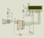
 

Please can someone help me on this case ....At first I thought it was a small project but it's becoming more complicated for me:bang::bang:
 

It isn't complicated, in fact compared to the project I'm currently working on it is VERY simple! The only problem is how to connect to the LCD. If it is a 'normal' LCD is doesn't use SPI, it is parallel and if you have enough pins on the PIC to connect to it , the software is even easier than SPI.

All we need to know for certain is how the LCD connects, the choice of PIC and the software can then be adapted to your needs.

Brian.
 

i think SPI (Serial Peripheral Interface)
uses Serial Data Out, Serial Data In, and Serial Clock
 

In your case PIC will be SPI master and LCD slave. So, you need CS (Chip Select) to select the Slave, MOSI (SDO), and SCK. MISO (SDI) is not needed. You need three pins for SPI communication.
 

1602 LCD uses parallel interface. You need 6 pins of PIC to interface 1602 LCD to PIC in parallel interface. So, you say that you are using SPI device between PIC and 1602 LCD and we want to know what SPI device that is. Better use I2C LCD. It needs only two pins. You can buy PCF8574 based I2C LCD modules from eBay and use them between PIC and 1602 LCD.

I2C LCD. You can buy similar on eBay.

https://www.banggood.com/IIC-I2C-1602-Blue-Backlight-LCD-Display-Module-For-Arduino-p-950726.html
 
Last edited:

ok it's true I just use I2C LCD I will also order
 

I see Paulfjujo in the other forum tells you exactly the same thing. When you have the SPI LCD you will have to tell us what format the commands to it are so we can advise on the software you need to drive it.

Brian.
 

I see Paulfjujo in the other forum tells you exactly the same thing. When you have the SPI LCD you will have to tell us what format the commands to it are so we can advise on the software you need to drive it.

Brian.

really I do not understand very well this question. As I saïd earlier, I am poor on this topic

- - - Updated - - -

really I do not understand very well this question. As I saïd earlier, I am poor on this topic

can you help me please

- - - Updated - - -

View attachment 118232 -(SCL) is the clock signal
-(SI) ist the data signal
- (CSB) activation signal
so a standard SPI I meant
and Sorry for the misunderstanding

I thought that this is the request format
 

I think that confuses things even more by using I2C instead of SPI !

Thierry, I will try to summarize:
1. The PIC only has 4 pins to connect to external circuitry. One of these is needed for the wind speed input so there are only 3 left to connect to the LCD.
2. A standard HD44780 LCD needs at least 6 connections (7 is better) to drive it. You can't connect two together or leave any disconnected.
3. There are ways to 'fake' the extra PIC pins you need by using an IC called a 'port expander'.
4. A 'port expander' works by using SPI (or I2C) to send the signals for the pins one at a time using 2 or 3 wires, in sequence, when all the pin signals have been sent it presents them all at the same time. SPI = "Serial Peripheral Interface" because it sends each bit serially. It captures all the bits, normally 8 bits sent one after the other then outputs them together on 8 individual pins. So effectively, it has expanded the 3 wires of the SPI interface to 8 parallel bits, this is enough to drive the LCD.

What we need to know is how the order of bits sent over the SPI wires correspond to the signals sent to the LCD.
For example: should the bits be sent D0,D1,D2,D3,EN,RW,RS or should they be sent RW,EN,RS,D3,D2,D1,D0 or some other way. The order of the bits decides which signals appear on which pins to the LCD so it is important we know so the software can be written to send them in the correct order. As the SPI board is built on the back of the LCD, the wiring is already fixed by the manufacturer, we need to know how they wired it so we can tell what bit order to use. There should be a data sheet with the LCD explaining the bit order to use.

Brian.
 

et is so RS R/W DB7 DB6 DB5 DB4 DB3 DB2 DB1 DB0

- - - Updated - - -

Does your ADC value converted to wind speed is Linear ? yeset is linear

- - - Updated - - -

and Usually 8 bit Microchip Port Expanders
 

Use the code I have posted with I2C LCD. If you use SPI LCD then with mikroC SPI Lcd8 library you need 5 pins to interface Port expander to PIC12f1840 and you can't do it because RA4 has to be used for ADC and RA3 is input only pin. You won't get 4 digital output pins.

- - - Updated - - -

Fixed the timer code.

I am using 500 ms interrupt. So count == 2 means 1 sec. For 1 minute count will be 120 and for 10 minutes it will be 1200 but adc is being read once every 15 seconds. Why ?

Code:
if(++count == 1200) {

and Usually 8 bit Microchip Port Expanders

No, 8 bit Prot Expanders if used then LCD interface with 6 or 7 pins that is RS, EN, D4, D5, D6, D7 connects to expander.
 

Attachments

  • Wind Speed Calculator rev2.rar
    121.5 KB · Views: 37
Last edited:

MikroC cannot compile for the PIC10F series which is what was originaly requested. There is little point in using a PIC12F1840 when at lower cost a PIC16F can be used and then there is no need for SPI anyway!

There are two options for programming the PIC10F220, one is to use assembly language, the other is to use Oshonsoft's "PIC10F simulator IDE" and program it in BASIC. It's a simple program either way, MPLABX can debug it in assembly language, Oshonsoft software can debug it in BASIC. MPLABX is free, Oshonsoft software is very inexpensive. Personally I would use assembly language but if you are completely new to programming you might find BASIC is easier.

Brian.
 

Thank you for your help but I must only use the PIC10F220 my request to change the pic has been rejected

sorry but I am very strong in structure language (Delphi Pascal) in LabVIEW, vision builder but not in assembly language because I did not study
This theme is part of a theme of an overall project that began all part Robotics and automation have been finalized and mounting excepting this theme in assembly and none of us knows if in Assembly language
Can anyone please help us with this program?
 

I will not write it for you but I will guide you to write it yourself.

You need the following before we start:
1. An assembler ! I strongly recommend you download MPLABX from https://www.microchip.com/pagehandler/en-us/family/mplabx/ it is big but free and works with all the PIC types. It is available for Linux, OSX and Windows platforms.
2. The data sheet for the 10F220, you can get this from the Microchip web site.
3. A schematic so you know which pins (port bits) connect where. I suggest GP0/ANO is used for the analog voltage input and GP1, GP2 used to drive the LCD.
4. Visit and save this page: https://www.circuitvalley.com/2011/12/two-wire-serial-lcd-16x2-graphics.html for info on 2-wire serial interfacing.
5. A Pickit2, Pickit3 or similar programmer unit. If you use an alternative make sure it can program a 10F220, some can't!
6. For hardware, you need the components on the Circuitvalley web page and the PIC of course. If possible get the DIL package type, they are easiest to handle.

The code itself is quite easy to write and debug but forget any ideas about structured languages, in assembly language you are working at the lowest possible level where you have to tell it absolutely every single step to take. Don't worry about it though, you will find it far more satisfying when you see it doing what you tell it instead of what someone else decided for you!

Brian.
 

Ok i have installed MPLABX and have the data sheet for the 10F220, !! with which we start? I guess with the initialization of pine and creates variable
 

You have to use this circuit. In ADC circuit you have to replace pot with RC filter. You just can't use SPI LCD with 10F220 because MCLR pin is input only pin and you need three output pins for SPI namely SCK, SDO and CS. You can ofcourse use Software I2C based 2 wire LCD interface or you can use the posted circuit.
 

Attachments

  • wsc.png
    wsc.png
    25.8 KB · Views: 53

Not so fast.... slow down...

The first thing to do is create a new project in MPLABX and copy the template file in to it. I'm assuming you are using Windows, the program is exactly the same in Linux and OSX but you may need to use different files and folder names.

1. open MPLABX and close the 'start' and 'store' windows.
2. click on 'File/New Project/Standalone project' then 'Next'.
3. click on 'Baseline 8-bit MCUs (PIC10/12/16)' and pick "PIC10F220" from the list, then 'Next'
4. select 'none' for the debug header then click 'Next'
5. in the 'select tool' menu, pick 'Simulator' then 'Next'
6. in 'Select compiler' pick 'mpasm (v5.62) [C:\Program Files\Microchip\MPLABX\v3.00\mpasmx]' then 'Next'
7. fill in 'Select Project Name and Folder' with a name and location to create the files. Leave 'Set as main project' checked and click 'Finish'

That sets up the IDE ready for your program.

Now we use a pre-built 'template' to make things easier.
8. click on 'File/New File' and in the 'Categories' select 'Assembler' then click 'Next'
9. change the file name to something more meaningful then click 'Finish'. This creates a blank source file for you.
10. Using the normal 'copy/paste', find the file called 'C:\Program Files\Microchip\MPLABX\v3.00\mpasmx\templates\Code\10F220TEMP.ASM' and copy it's entire contents to the MPLABX window.

Finally, click on the hammer icon 'Build Main Project' and it should create your first 10F220 program. It needs the extra code of course but let me know if you get that far.

Brian.

yes i did and Build Main Project'
 

Status
Not open for further replies.

Part and Inventory Search

Welcome to EDABoard.com

Sponsor

Back
Top