bhoobalan
Member level 1

- Joined
- Dec 28, 2013
- Messages
- 35
- Helped
- 1
- Reputation
- 2
- Reaction score
- 1
- Trophy points
- 8
- Activity points
- 280
Hello friends,
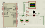
I am generating pwm signal in CCP1CON and CCP2CON of PIC16F877A controller and also i connected two led's across the pin with resistor's. I am getting output in the oscilloscope but the led's are blinking, why the led's are blinking?
How should i rectify the blinking of led's? There is a voltage variation also why it happens?
I have attache my code and circuit diagram.
Pls reply me
Thank you