milan.rajik
Banned
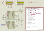
Is this SPI Multi-Master Communication working properly ?
Please see the image. There are some zeroes shuttling. Are there zeroes present because after 1st SPI communication the SSPBUF got cleared and it is shuttling in further SPI communications ?
broken link removed
Please see the image. There are some zeroes shuttling. Are there zeroes present because after 1st SPI communication the SSPBUF got cleared and it is shuttling in further SPI communications ?
broken link removed
Attachments
Last edited by a moderator: