Welcome to our site! EDAboard.com is an international Electronics Discussion Forum focused on EDA software, circuits, schematics, books, theory, papers, asic, pld, 8051, DSP, Network, RF, Analog Design, PCB, Service Manuals... and a whole lot more! To participate you need to register. Registration is free. Click here to register now.
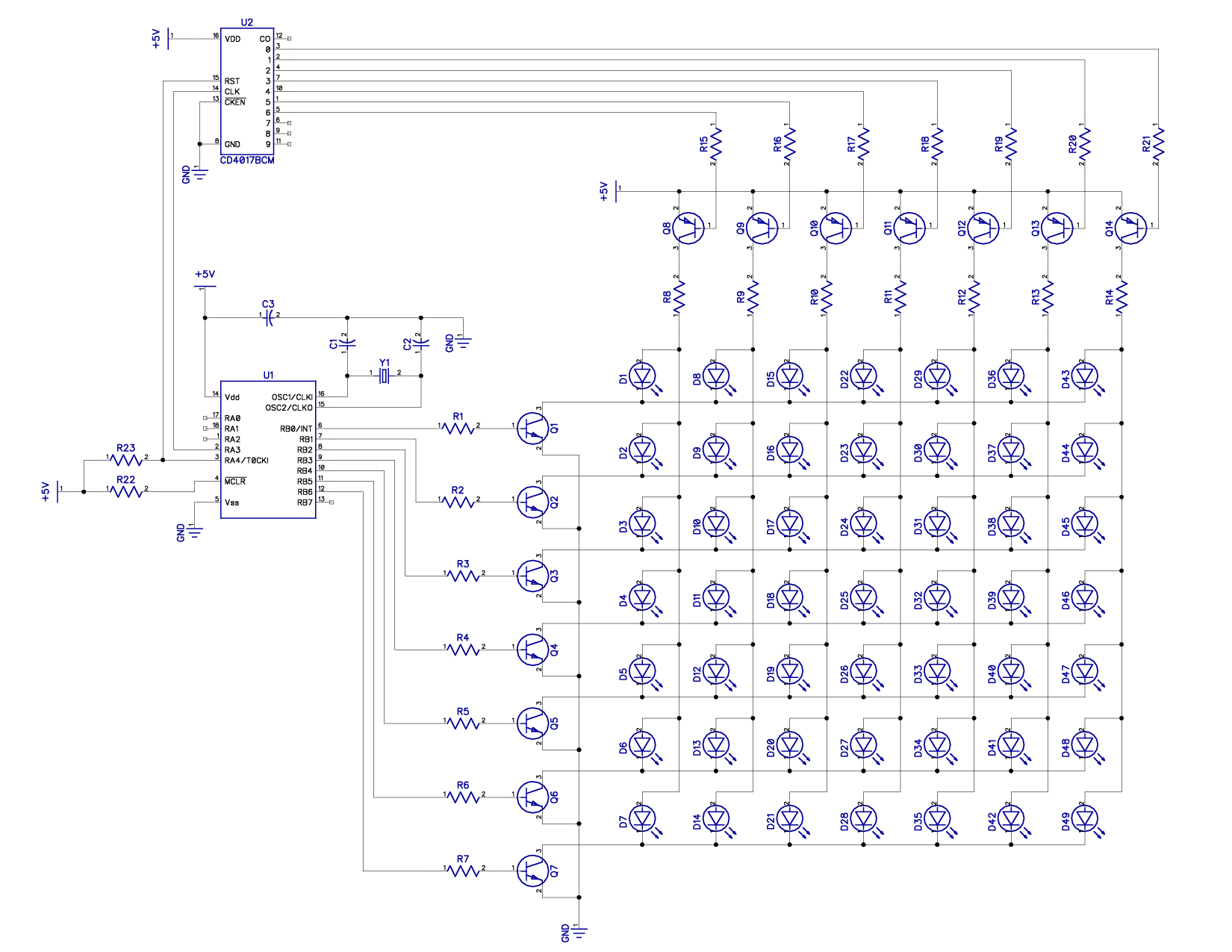
I have developed other electronic projects but this one here is new for me...I don't have a clear understanding driving a transistor with a pic. Will this circuit work?
Agreed - it does look as though the column drive signal is inverted though. The CD4017 has active high outputs so at the moment it turns all columns except one on at the same time, that's probably the opposite of what you want.
Besides wrong mux counter output polarity, if you want to light more than one LED in a column, the series resistors should be connected to the row rather than the column transistors, otherwise the current will be shared by a varying number of LEDs and cause intensity variations.
This site uses cookies to help personalise content, tailor your experience and to keep you logged in if you register.
By continuing to use this site, you are consenting to our use of cookies.