Continue to Site

Welcome to EDAboard.com

Welcome to our site! EDAboard.com is an international Electronics Discussion Forum focused on EDA software, circuits, schematics, books, theory, papers, asic, pld, 8051, DSP, Network, RF, Analog Design, PCB, Service Manuals... and a whole lot more! To participate you need to register. Registration is free. Click here to register now.

PIC analog input and digital output on the same PORT

Status
Not open for further replies.

shsn

Junior Member level 3
Joined
Nov 28, 2012
Messages
26
Helped
0
Reputation
0
Reaction score
0
Trophy points
1,281
Activity points
1,523
I am having difficulties having both analog input and digital output on the same port on PIC16F716.
On PIC16F716, PORTA (5 pins) can be used for both analog inputs or digital inputs. I would like to have;
RA0/AN0 as analog input and RA2/AN2 as digital output which will be connected to an LED.

Code:
void main() {
     TRISA = 0x02;                    // Initialise PORTA RA2 as INPUT, rest as OUTPUT
     TRISB = 0;                         // Initialise PORTB as OUTPUT
     PORTB = 0;                        // Set PORTB as OUTPUT
     do {
        adc_val = ADC_read(1);
        volts_m = (long)adc_val*5000/256;
        driveLED (volts_m);
     }
     while(1);
}

Although RA1/AN1 is correctly set as analog input (because it works according to driveLED function) but the LED connected to the RA2/AN2 is not doing anything.
Can anyone point me to the right direction?

Thank you.
 

I'm not sure how can you send the long 'volts_m' value to driveLED function. Just try simple program to glow the led on pin RA2.
Please specify what compiler are you using?

if using ccs c compiler, use this

use the line
HTML:
output_high(PIN_A2);

instead of
HTML:
driveLED (volts_m);
 

You haven't shown the driveLED function. So, we don't know what's happening there.

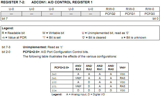
As for RA2/AN2, you need to make it digital by setting ADCON1 appropriately.

Add this line to your code:
Code:
ADCON1 = 4;
This will make AN2 digital and AN0, AN1 and AN3 analog.

Here's how it should be:
Code:
void main() {
     TRISA = 0x02;                    // Initialise PORTA RA2 as INPUT, rest as OUTPUT
     [B]ADCON1 = 0x04;[/B]                 // AN2 Digital
     TRISB = 0;                         // Initialise PORTB as OUTPUT
     PORTB = 0;                        // Set PORTB as OUTPUT
     do {
        adc_val = ADC_read(1);
        volts_m = (long)adc_val*5000/256;
        driveLED (volts_m);
     }
     while(1);
}

ADCON1 register (from the datasheet):
5403661300_1354695666.png


Hope this helps.
Tahmid.
 

Status
Not open for further replies.

Similar threads

Part and Inventory Search

Welcome to EDABoard.com

Sponsor

Back
Top