Continue to Site

Welcome to EDAboard.com

Welcome to our site! EDAboard.com is an international Electronics Discussion Forum focused on EDA software, circuits, schematics, books, theory, papers, asic, pld, 8051, DSP, Network, RF, Analog Design, PCB, Service Manuals... and a whole lot more! To participate you need to register. Registration is free. Click here to register now.

PIC 16f877a Timer0 Operation

Status
Not open for further replies.

picmanpad

Newbie level 4
Joined
Jul 11, 2012
Messages
7
Helped
0
Reputation
0
Reaction score
0
Trophy points
1,281
Activity points
1,328
Hi

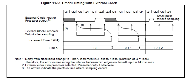
Please look at the attachment
As per the figure in the T0CKI High Pulse Width it takes No (Prescaler 0.5TCY + 20) times
that mean to capture the High Pulse Width of external clock, the MCU takes 0.5TCY + 20 times

This is related to pic16f877a
It would be much appreciated any one can explain this scenario

tmr0.JPG
 
Last edited:

As per the figure in the T0CKI High Pulse Width it takes No (Prescaler 0.5TCY + 20) times
that mean to capture the High Pulse Width of external clock, the MCU takes 0.5TCY + 20 times

This is related to pic16f877a
It would be much appreciated any one can explain this scenario

View attachment 77078

Instruction cycle period (Tcy) equals four times the input oscillator time base period. All specified values are
based on characterization data for that particular oscillator type, under standard operating conditions, with
the device executing code. Exceeding these specified limits may result in an unstable oscillator operation
and/or higher than expected current consumption. All devices are tested to operate at “min.” values with an
external clock applied to the OSC1/CLKI pin. When an external clock input is used, the “max.” cycle time
limit is “DC” (no clock) for all devices.

Tcy represent the Instruction Cycle Time/Period or Tcy = 4/Fosc, therefore if No Prescaler is set the minimum External Clock Width is 0.5*Tcy + 20ns.

For Example:

Fosc = 4MHz, Tcy = 1us,

0.5(1us) +20ns = 520ns minimum pulse width


BigDog
 
hi
as per data sheet
External Clock Synchronization
When no prescaler is used, the external clock input is the same as the prescaler output. The synchronization
of T0CKI with the internal phase clocks is accomplished by sampling the prescaler
output on the Q2 and Q4 cycles of the internal phase clocks (Figure 11-5). Therefore, it is necessary
for T0CKI to be high for at least 2Tosc (and a small RC delay of 20 ns) and low for at least
2Tosc (and a small RC delay of 20 ns). Refer to parameters 40, 41 and 42 in the electrical specification
of the desired device.

What is this Clock Synchronization????
 

Essentially Clock Synchronization is the synchronization of the T0CKI External Clock pulse with those pulses of the System Clock Fosc, where Tosc is the Period of the System Clock Fosc. The Q1, Q2, Q3 and Q4 represent the four System Clock Fosc pulses which occur within Instruction Cycle Time/Period Tcy.


Notice how the Timer0 incrementation occurs at the leading edge of Q4, which is the leading edge of the fourth cycle of System Clock Fosc.


BigDog
 
hI Bigdog

As per your reply in post#4
0.5(1us) +20ns = 520ns minimum pulse width
This is the Maximum frequency Timer0 can capture 1/1040ns , I think in other word the Timer0 takes 1040ns time to capture single pulse of it's maximum frequency
 

Yes and no, the minimum pulse width ensures the pulse is active during specific events, otherwise as the attached picture indicates there is a chance a pulse width below the minimum could occur and go undetected/sampled. However, if a pulse less the minimum width were to occur at the appropriate time it may actually trigger an increment of the Timer0. The specs of the datasheet specify the minimum requirements to ensure the pulse indeed is detected and the Timer0 incremented.

Therefore, yes to ensure the proper operation of the Timer0, the frequency of the external clock must be less than approximately 962kHz with a 50% duty cycle.

I might also add, if you examine the specs of Timer1, you will notice unlike Timer0, it can operate with an external clock in an Asynchronous Mode.


BigDog
 
Hi Bigdog
"the external clock input is divided by the asynchronous ripple-counter prescaller so that the prescaller output is symmetrical"

I found above sentence in the PIC mid range Manual, so I would like know that what is the capability that ripple counter has to capture clocks at 20ns delay with out rescaller it needs 0.5tcy+10ns

And also I found in one website about timer prescaller and postcaller which is 1:1, 1:2, 1:4, 1:8 and
1÷1,1÷2,1÷4,1÷8 I think both are the same result
 
Last edited:

Status
Not open for further replies.

Similar threads

Part and Inventory Search

Welcome to EDABoard.com

Sponsor

Back
Top