Continue to Site

Welcome to EDAboard.com

Welcome to our site! EDAboard.com is an international Electronics Discussion Forum focused on EDA software, circuits, schematics, books, theory, papers, asic, pld, 8051, DSP, Network, RF, Analog Design, PCB, Service Manuals... and a whole lot more! To participate you need to register. Registration is free. Click here to register now.

PIC 16F877A ADC Help Required

Status
Not open for further replies.

chi239

Newbie level 6
Joined
Sep 13, 2010
Messages
11
Helped
0
Reputation
0
Reaction score
0
Trophy points
1,281
Activity points
1,388
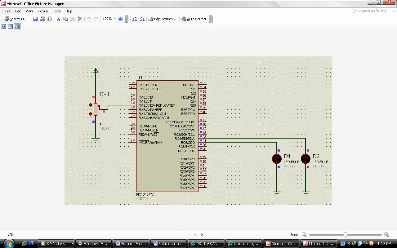
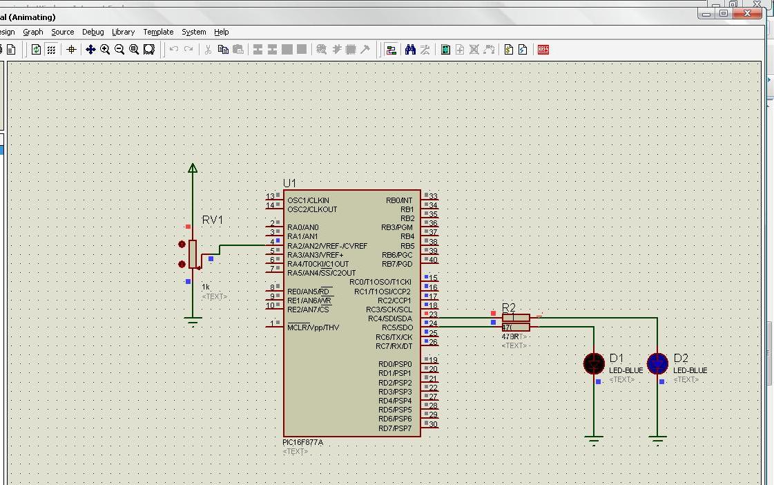
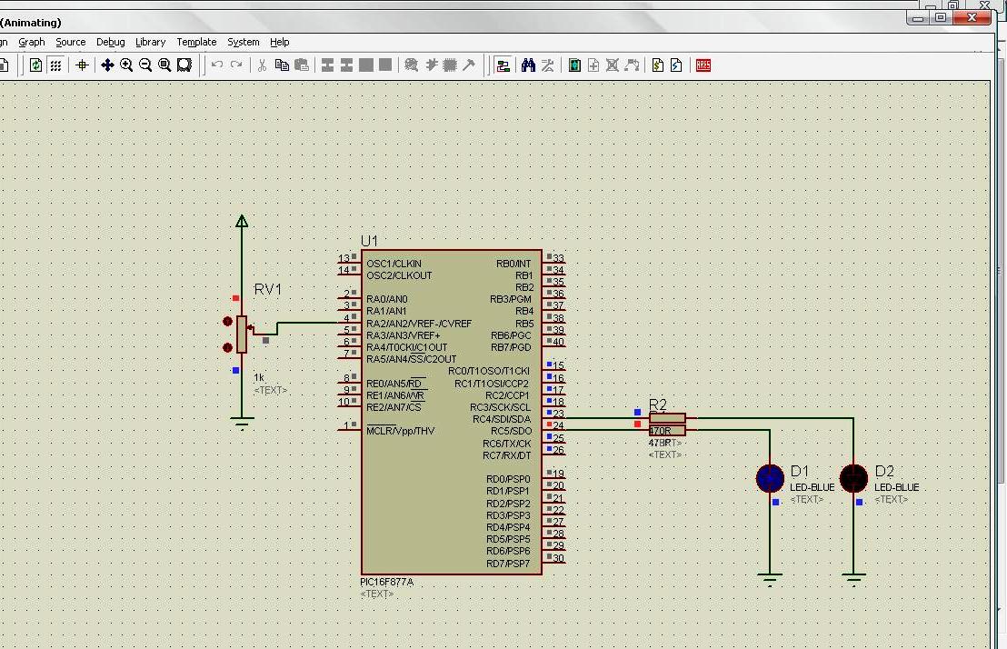
I am a beginner. I am developing a card around the PIC16F877A (4MHz). I want to use the ADC (single-channel) with AN0 as the input. All other PortA pins are to be used for Digital I/O. I am having trouble in configuring the ADC. I am using ADCON0=0x85, ADCON1= 0x8E and TRISA=0x01, but this does not seem to work. I am using the MikroC Compiler. Can anyone help me, please?
 

Hi,
Since you're using mikroC, you can do this:
Code:
//ADC Initialization
ADCON1.PCFG3 = 1;
ADCON1.PCFG2 = 1;
ADCON1.PCFG1 = 1;
ADCON1.PCFG0 = 0;
PORTA = 0;
TRISA = 1;
//Initialization done (enough for mikroC)
When you need to read it from ADC, you can simply do it like:
Code:
ADCR = ADC_Read(0); //ADC channel 0 is read, converted to digital and stored in ADCR

Hope this helps.
Tahmid.

---------- Post added at 11:44 ---------- Previous post was at 11:44 ----------

For help in your code, you need to upload your code so that we can find out where the mistake is.
 
  • Like
Reactions: Tiabak

    Tiabak

    Points: 2
    Helpful Answer Positive Rating
Hello every1....i have similar problem, and i hope i can get some help when iserch in forum ifound code for adc but without schema i desgin one in protues isis
but isn't work please help me......


1.Im using PIC16F877A MCU, and I want to change the format of a code which do the following:
1/ convert the analog voltage received in PortA.2 (pin 4) to digital.
2/ if the analog voltage is less than 2V and more than 1V...set PortC.4 (pin 23).
3/ If analog voltage is less than 1V...set PortC.5 (pin 24).
code:
unsigned int t;

void main() {
ADCON1 = 0x80; // Configure analog inputs and Vref
TRISA = 0xFF; // PORTA is input
TRISC = 0; // PORTD is output

while (1)

t = Adc_Read(2); // get ADC value from 2nd channel

if(t >= 0 & t <= 410){
PORTC= 0b00010000;
}
else if (t >= 411 & t <= 615 ){
PORTC= 0b00100000;
}
else PORTC = 0; }


Hi,
The ADC output is 10-bit, so change your code to:
Code:
unsigned int t;

void main() {
ADCON1 = 0x80; // Configure analog inputs and Vref
TRISA = 0xFF; // PORTA is input
PORTC = 0;
TRISC = 0; // PORTD is output

while (1){

   t = Adc_Read(2); // get ADC value from 2nd channel

   if(t >= 0 & t <= 205){
      PORTC= 0b00010000;
   }
   else if (t >= 206 & t <= 410 ){
      PORTC= 0b00100000;
   }
   else PORTC = 0; 
}
}

You also didn't connect a resistor between LED and PIC. Connect a 470R resistor between each LED and PIC pin.

Hope this helps.
Tahmid.
 
Thank you Tahmid. I will try it out later today and get back to you.
 

Sorry Tahmid. I tried it, but it doesn't work. Don't you think we should initiallize ADCON0 also?

The funny part is - if I try ADCON0=0x85, ADCON1= 0x80 and TRISA=0x01, it works with AN3 as input. But then all other PORTA pins also become inputs. I want to use the other PORTA pins as digital outputs.

Please shed some light on this.
 

Thank you very much Tahmid,

It worked now

I'm sooo happy. Those two lines gave me headache for days...

Thanks.


Hello Tahmid,

Do you think I need to use the ANSEL command?
 

Hi,
I don't think so. ANSEL is not for PICs like 16F877A. It's only for the newer chips like 16F887. I'm working on a PC where mikroC isn't available or installed. I'll post the Proteus file once I go home and run my PC.
 
Hey Tahmid, I got the thing to work after all. It looks like to AN0 pin was defective :-( I changed the microcontroller and your code worked like a dream! Thanks a zillion, mate! Cheers!
 

Hello Tahmid, I need your help again. I have to pick up 5 analog values, one after the other. (With the 10-bit ADC in the 16F877A, these will obviously lie between 0 and 1023). Now, I need to check whether each of these values lies within a specified band. If not, then an output should be activated.

For example, if the 1st value lies within the 555 and 600, we proceed with the next value, otherwise we make port C.5 high for about 50 mSecs and proceed with the 2nd value which may have to lie between 200 and 220, and so on....

Thus for 5 values, we will most probably need to have an array with ten values. Can you guide me how to go about this.

Can you also give me your e-mail address or Skype ID?

Thanks & Regards.

Deepak
 

hello Tahmid you are looks like good engineer iwant your help in this;
hi guys sorry for this stupied question but iam new un micro controller i use
PIC16F877 and iwant to write acode for example if the temperture exceed specific value for example 25 the led is on or fan is work note that iuse comparator as switch

and i use micro c or micro pro and i use comparator and i want use pins:RA0-RA3
pins:RA4-RA5 AS output

I know it's late, but do you still need help with it? Then I can help.
 

Status
Not open for further replies.

Similar threads

Part and Inventory Search

Welcome to EDABoard.com

Sponsor

Back
Top