Continue to Site

Welcome to EDAboard.com

Welcome to our site! EDAboard.com is an international Electronics Discussion Forum focused on EDA software, circuits, schematics, books, theory, papers, asic, pld, 8051, DSP, Network, RF, Analog Design, PCB, Service Manuals... and a whole lot more! To participate you need to register. Registration is free. Click here to register now.

[SOLVED] Pic 16f876a Pure Sinewave inverter

Status
Not open for further replies.
some body please answer my previous two posts.

jagspaul
 
  • Like
Reactions: yellow

    yellow

    Points: 2
    Helpful Answer Positive Rating
Hi jagspaul,
sorry, but I can't answer to all your questions. I will try to answer only to your most important questions.
First, yes you are right for "a" and "b"channel confusion. I am reading the "b" channel in "volt_a" variable and the "a" channel in "volt_b" variables, but this is not important for proper work of inverter. If you want just swap the volt_a with volt_b variable in software.
"A" (a) and "B" (b) voltage levels are readed and checked only over low frequency (50Hz) controlled MOSFETs - Q5 and Q6 for "B" signal (at the positive half sine-wave, PIN_C1 = 1), and Q7 and Q8 for "A" signal (at the negative half sine-wave, PIN_C1 = 0).
Second, the U1B with resistor R8 (100 Ohm) and U1C with resistor R18 (1.5 kOhm) forms a two separate current to voltage converter circuits, U1B wirt R8 - for high current measuremet (Curr_h), and U1C with R18 - for low current measurement (Curr_h).
Curr_h signal is using for current protection of the inverter, and Curr_l signal is using for switching between Normal <-> StandBy modes.

Best regards,
Taner
 
Hello Taner

Thank you for your response.

One more question, please go through the sample code of your program below.

output_low(PIN_C3);
set_adc_channel(stdby_chan); // check vref value;
delay_us(10);
for(i=0; i<32; i++) {
volt_ref=read_adc();
volt_ref_temp+=volt_ref;
if(i==31) {
volt_ref_avg=volt_ref_temp>>8;
volt_ref_delta=volt_ref_avg-29;
volt_ref_temp=0;
}

You have taken 32 samples and to make average voltage the code should be
volt_ref_avg=volt_ref_temp>>5; but in your program I found volt_ref_avg=volt_ref_temp>>8;
I don’t understand the valid reason. Please explain.

Thanks and regards
Jags
 

Hello Friends,

After modification of the soft I have finally a pure sine wave of 50 Hz on the output

Pierre
 

Attachments

  • photo043_6343.jpg
    photo043_6343.jpg
    560.9 KB · Views: 493
doc007 said:
Hello Friends, After modification of the soft I have finally a pure sine wave of 50 Hz on the output. Pierre
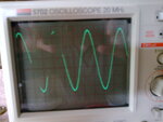
Congratulations for so far, Pierre. I'm going to make a printout of the software, to get more involved.
At.
 
  • Like
Reactions: yellow

    yellow

    Points: 2
    Helpful Answer Positive Rating
Hello Friends,

After numerous tests I come to following conclusions :

-1) The a/b voltage check is well working in pwm norm,pwm stop, pwm stdby but not in pwm start. Why ??????? If somebody has a solution ?

-2)During positive sine half wave we can only test b/voltage and during negative sine half wave we can only test a/voltage.
In effect if I want to test b/voltage while negative sine half wave or a/voltage while positive sine half wave by changing MuxA or MuxB I have the high-levels of signals 'a' and 'b' on pin 2 of PIC MCU and not the low-levels.( test a and b not possible )

Am I wrong ?
Friendly
Pierre
 

Hi Pierre

Congratulations.
Could you share what are the modification have you done in soft with us??

Regards
Jags
 

Hello Jags
If I link a to pin2 and b to pin1 of MC 14053 I use this version
Pierre
 

Attachments

  • sine_pwm_6266.doc
    29.8 KB · Views: 606

doc007 said:
After numerous tests I come to the following conclusions :
-1) The a/b voltage check is well working in pwm norm, pwm stop and pwm stdby but not in pwm start. Why?
-2) During positive sine half wave we can only test b/voltage and during negative sine half wave we can only test a/voltage.
In effect if I want to test b or a/voltage by changing MuxA or B, I have the high-levels of 'a' and 'b' on PICpin2, and not the low-levels.
Am I wrong ? Pierre.
Pierre, am I right that the above modified quote is what you are asking?
Why should you change muxA/B? In normal use, the output from the two bridges (a and b) is an indication that they are working (no zero voltage). Only during startup the integrated (b/a) signal from LM324M is not present for a while. Later on, the signal says that the two bridge-halve's are switching.
I don't know if the software also checks for a "stick to high" level, which is also a defect bridge of course.
So at start-up, zero b/a is ok, then after initiatiation an analog value is ok (maybe 3v?) and too high is not ok (regulate pwm down, as reaction), also too low is not ok (means overload).
At.
 

Hello At


Taner wrote
b/a signal (pin2 - RA0/AN0) must include only a low levels of the separeted 'a' and 'b' signals (pin2 and pin1 - U10). If b/a signal include only a high-levels of signals 'a' and 'b', then you must change a connection places of this two signals to pin1 and pin2 of the U10 (a<->b and b<->a).

Therefore the software checks only the low level from a or b with in soft a/b max = 96 --> 5/255*96 = 1.8V.

Only during the first positive hemi wave ( pwm start) the a/b test is higher than a/b max ( 1.8 V ) and I don't understand why ?

Pierre
 

@t said:
So at start-up, zero b/a is ok, then after initiatiation an analog value is ok (maybe 3v?) and too high is not ok (regulate pwm down, as reaction), also too low is not ok (means overload).
I'm not sure anymore that the above is right. Because the a and b signals are clipped with zeners to +5.1v, they can't be regarded as analog (which goes to +12).
So probably they are treated as a digital sign that the voltage is there, or not.
Taner means that while a is high, b = low (and vice versa), and that it must correspond with the right mux pins, so that it corresponds with the softwarecheck for zero (low). I should not change the mux/A and mux/B connections to achieve that, but exchange the actual a and b lines (if neccesary).
I don't understand the count level used in these checks, that suggests analog handling?

Pierre said:
Only during the first positive hemi wave ( pwm start) the a/b test is higher than a/b max ( 1.8 V ) and I don't understand why
Maybe here (in pwm start) not "zero" is demanded, but a higher value is allowed because the cyclus is starting up.
Strange that the test is for low (zero), it should be more clear if it was inverted and tested for high.

Correct me if I'm wrong, these are my 2 cents, At.
 

To obtain the max power of this inverter i will never find a trafo 8V/230V 600 Watt. Can I replace it by 2 trafos 300 Watt in parallel or 3 trafos 200 watts in parallel

particular assemblage because induction ?

Pierre
 

doc007 said:
// Can I replace it by 2 trafos 300 Watt in parallel or 3 trafos 200 watts in parallel ? // Pierre
Yes, that's no problem Pierre.
By the way, why do you especially want pure sinus, otherwise a modified sinewave converter would be much smaller (high freq. trafo).
At.
 

Hello Taner or
Somewhere who has finished the inverter,

Have you found a trafo 8V/230V 600W and where ?
It seems to be better to use one trafo rather than 2 or 3 in parallel.
Thank you for the answer

Pierre
 

Hello Friends,

Has noboby found a trafo for this project ?

Pierre
 

Hello doc007,
600W is too much for 12V battery (Iin > 50Adc). And this inverter can not work in continuous mode operation supplying 600W power with 12V battery. Normally can supply approx. 350-400W in continuous mode operation (Iin ~ 35Adc).
Trafo's primari voltage can be from 6 to 8 Vac. Output voltage regulator will be care and will adjust output voltage to 220Vac.

Best regards,
Taner
 

Hello Taner

Hi friends,
Yes, maharadga is right, there have an error in schematics.
Please accept my apologies for this error. It happened when I redraw the schematics from original one. In the original schematics the anods of two bootstrap diodes (D6 and D7) are connected to the output of LM317T, but then this voltage should be min. 10V (minimum supply voltage requirements for optodriver TLP250). Old shematics was designed for 24V accumulators. And the output voltage of LM317T was 12V.
In case of 12V accumulator we should replace LM317 with LDO voltage regulators for 10V output voltage (some like LM2940LD-10).

To have more current, can you send to me the original schematic for 24 V accumulator.
If you don't have more the schematic , please can you at least send me the bootstrap system with 24V.
What will be the voltage on A and B.
How much power can I hope ?
IRL3803 seems to be correct for the full bridge.
Of the side of the MCU I can adapt V_Batt.

Thanks for you reply
Friendly
Pierre
 

doc007 said:
Hello Friends, has nobody found a trafo for this project ? Pierre
Only for 300W Pierre, 2x 10,5v to 230v. Torroid model.
At.
 

Hello Friends,

I'm still looking for my transformer.

By waiting I have begin for my solar system the building of a regulator 12 V based on pic .
The PWM of 100 kHerz will drive one converter Buck.
To drive the power mosfet I am looking for a Trafo HF with ratio 1:2.5
Effectively my pulse has 4.5 V and I must have 12 V to drive the power mosfet.
Has somebody an idea where I can find this type of trafo ?
Thanks for the answer

Pierre
 

Status
Not open for further replies.

Part and Inventory Search

Welcome to EDABoard.com

Sponsor

Back
Top