sarathsnairpoonjar
Member level 2
- Joined
- Nov 12, 2012
- Messages
- 50
- Helped
- 2
- Reputation
- 4
- Reaction score
- 2
- Trophy points
- 1,288
- Location
- Cochin,Kerala,India
- Activity points
- 1,560
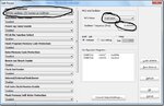
i want to use pic's internal oscillator,but dont know how to set it in mikroc pro
please help me
please help me