Continue to Site

Welcome to EDAboard.com

Welcome to our site! EDAboard.com is an international Electronics Discussion Forum focused on EDA software, circuits, schematics, books, theory, papers, asic, pld, 8051, DSP, Network, RF, Analog Design, PCB, Service Manuals... and a whole lot more! To participate you need to register. Registration is free. Click here to register now.

Photodiode/Multisim Help needed.

Status
Not open for further replies.

USMCinfinity

Member level 1
Joined
Jul 13, 2010
Messages
38
Helped
0
Reputation
0
Reaction score
0
Trophy points
1,286
Location
Puerto Rico
Activity points
1,509
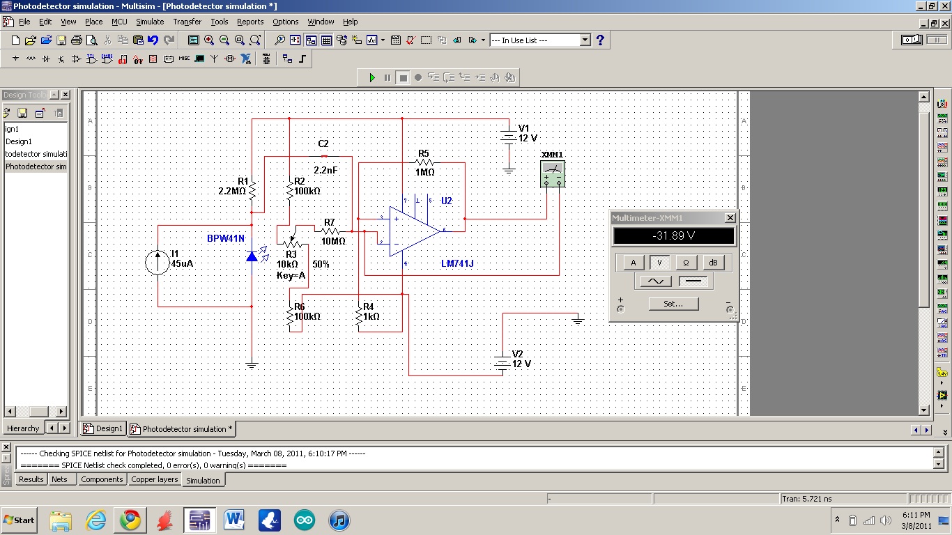
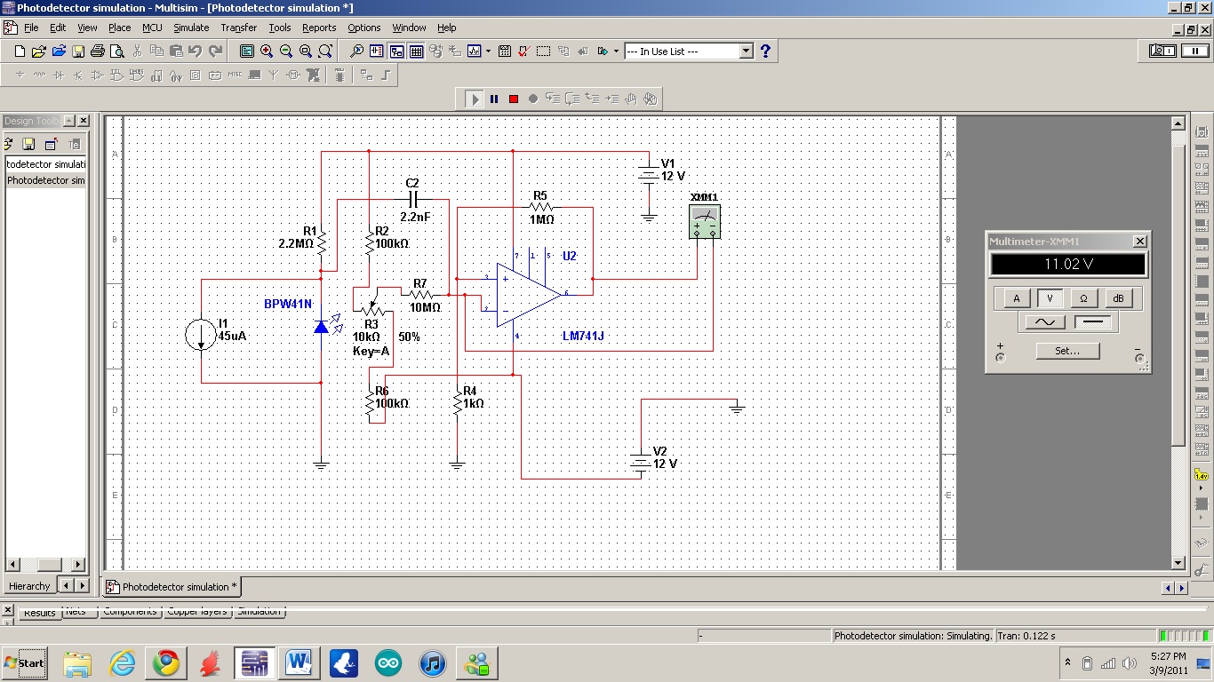
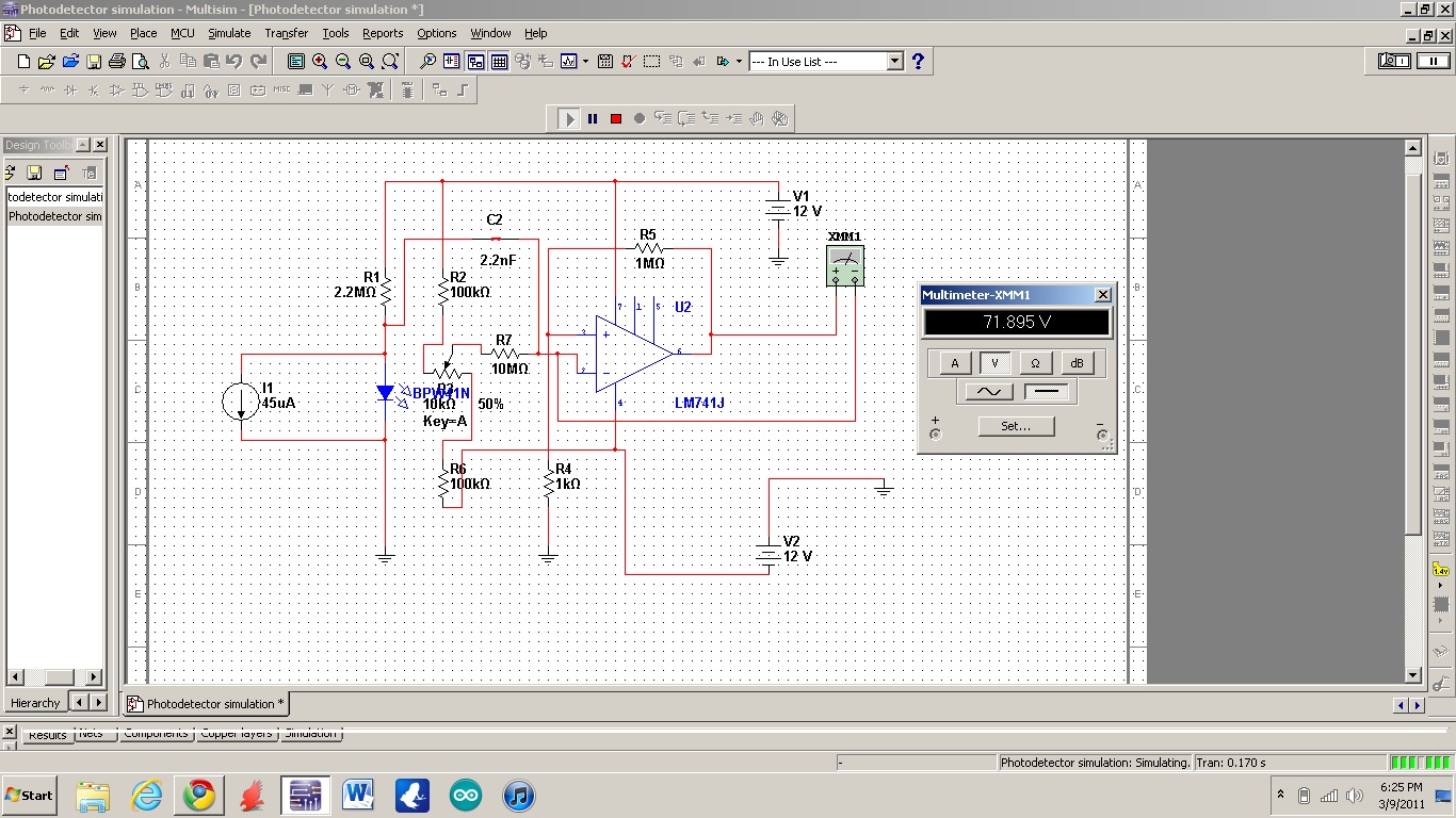
Can someone tell me whats wrong with this circuit? ...Please don't be harsh, I'm very tired. Every time I click play the capacitor goes bye bye.


Are you sure that the R4 resistor should be connected between the positive input and negative power supply (instead of ground)

Alex
 
Are you sure that the R4 resistor should be connected between the positive input and negative power supply (instead of ground)
Also besides this point, I'm unable to detect a reasonable circuit operation, You should explain first what you are trying to achieve. If the 45 uA current source is intended as photo current simulation, at has the wrong polarity.
 
I'm trying to simulate this circuit.

Here it is with what you guys told me, the current isn't really doing anything...


Here it is with what you guys told me, the current isn't really doing anything...

Read again this comment

If the 45 uA current source is intended as photo current simulation, at has the wrong polarity.

I have seen a circuit using a photodiode but it was actually reversed as FvM said

photometer2simple.jpg

Alex
 

I did change the polarity in the other one I put. Changing the diode's polarity too gives the result below.


What is the output you expect from the circuit?
Why is the multimeter connected between the negative input of the opamp and the output?

Alex
 

You have now presented three different photodiode/OP connection variants. One of them (the second) is correct in so far, that the current source places the photodiode in forward bias. But the overall circuit is still wrong, as Alex mentioned in his first post. Unfortunately we don't knów, what you exactly want to achieve.
 

Status
Not open for further replies.

Similar threads

Part and Inventory Search

Welcome to EDABoard.com

Sponsor

Back
Top