Continue to Site

Welcome to EDAboard.com

Welcome to our site! EDAboard.com is an international Electronics Discussion Forum focused on EDA software, circuits, schematics, books, theory, papers, asic, pld, 8051, DSP, Network, RF, Analog Design, PCB, Service Manuals... and a whole lot more! To participate you need to register. Registration is free. Click here to register now.

Photodiode amplifier problem

Status
Not open for further replies.

Miltaridis

Newbie level 6
Joined
May 21, 2011
Messages
14
Helped
0
Reputation
0
Reaction score
0
Trophy points
1,281
Location
Xanthi GR
Activity points
1,378
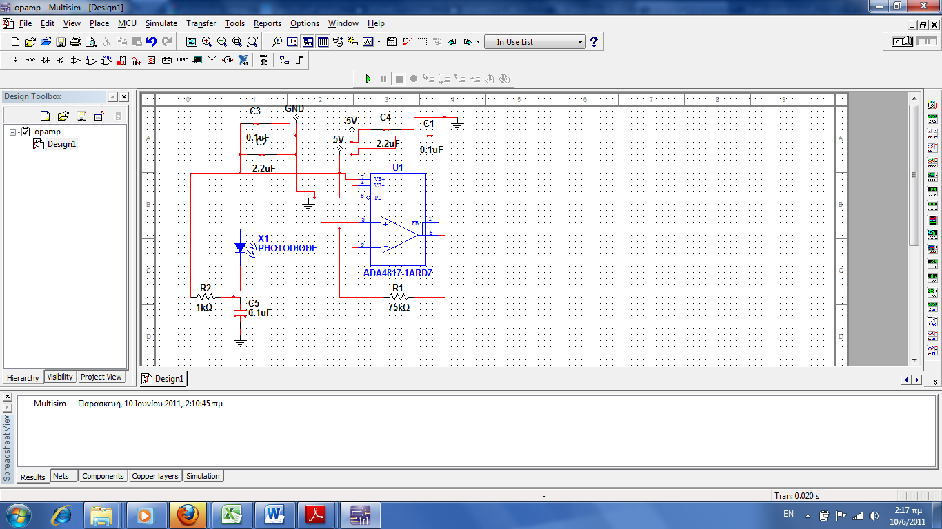
]I am using a pin photodiode bpw24r along with op amp ada4817 wired as a transimpedance amplifier. By biasing the diode at 5v my datasheet gives me a capacitance of 3.8 pf which combined by a feedback resistor of 75K with the rest of the circuit would give me a bandwidth at about 20MHZ .
My photodiode datasheet also states that the photodiode has a leakage current of about 2-10nA. So i assume that this current would be amplified by the feedback resistor and i would get about 750μV offset due to leakage current.Moreover the biasing current is in the pico range so it shouldnt create any offset too.
When i transmit a random Manchester modulated at 2MHZ signal i get the signal with a little bit distorted but with a major offset of about 200mv and my singal ptp at 800mv.
Here is my schematic .

Can someone point out the source of this noise ?
thx in advance
 

A offset won't be considered as noise. May be I just don't understand your signal description.

A transimpedance amplifier with a GHz amplifier and no feedback capacitance can't result in stable operation, however.
 

Well i am using the stray capacitance of the resistor which is about 0.2pf to eliminate noise gain peaking. By offset i mean that my signal which comes by the way inverted extends form -200mv to- 800mv and i would expect it to range from 0mv to 600mv .
Thanks for your quick reply
 

Well i am using the stray capacitance of the resistor which is about 0.2pf to eliminate noise gain peaking.
So it's a rather large resistor package.
i would expect it to range from 0mv to 600mv.
Me too at first sight. Maybe it's due to photodiode behavior? If would like to see the amplifier impulse response for an optical pulse of longer duration.

By the way, if you are using a 10:1 oscilloscope probe, are you sure about it's correct frequency compensation?
 

It might be worthwhile reducing your feedback resistor value and see what happens.

Also, are these simulated or practical results? With 75k feedback the overall performance will be too slow for a 2MHz square wave signal I think.

You cannot rely on stray capacitance for compensation. Also, what is the speed of the oscilloscope you are probing with (assuming you have built it)? A high frequency oscillation will often look like a DC offset on a slow oscilloscope.

Keith.
 

Well i tried reducing the feedback resistor got improved ,bandwidth but still the same offset problem.

Using a large compensation capacitator puts a pull in the frequency response restricting bandwidth. Still i tried putting a very large compensation capacitator and i got only the offset..?

My oscilloscope is at 100MHZ but i dont think its an oscillation, because the large compensation capacitator would have killed it .

Frequency compnsetaion sorry but i have no knowledge about this

Thanks for your time
 

Remove the photodiode and see if the offset goes. Is it in total darkness? Is it connected the correct way round (unlikely to be wrong otherwise the output would be a lot worse).

Keith

---------- Post added at 11:18 ---------- Previous post was at 11:16 ----------

By the way, I wouldn't guarantee that a large compensation capacitor would prevent oscillations depending on your PCB layout and capacitor values & types. Is this on a PCB with good ground plane and well decoupled?

Keith
 

I think its signal related because if i dont target the beam i get no offset..About the ground plane and decoupling i done my best i am not any kind of expert just a univeristy student

thank you for your time

---------- Post added at 14:02 ---------- Previous post was at 13:37 ----------

Well got a strange, clue, with the power off op amp's exit, gives around +200mv ...
 

Frequency compnsetaion sorry but i have no knowledge about this
My question only applies, if you are using a voltage diving (usually 10:1) probe. In this case, refer to your oscilloscope manual, most oscilloscopes have a test output for probe compensation.

My preferred oscilloscope connection would be a 450 ohm series resistor at the amplifier output, a 50 ohm cable and 50 ohm termination at the oscilloscope. You can be sure to get a flat frequency response up to GHz and no probe compensation errors.

I would also like to remember my suggestion to check the pulse response over a longer period of time.

After removing the diode, as Keith suggested, you would need to couple a signal generator to the amplifier, preferably through a resistor. Or perform this measurement with the diode in place.
 

Status
Not open for further replies.

Similar threads

Part and Inventory Search

Welcome to EDABoard.com

Sponsor

Back
Top