Continue to Site

Welcome to EDAboard.com

Welcome to our site! EDAboard.com is an international Electronics Discussion Forum focused on EDA software, circuits, schematics, books, theory, papers, asic, pld, 8051, DSP, Network, RF, Analog Design, PCB, Service Manuals... and a whole lot more! To participate you need to register. Registration is free. Click here to register now.

phase shifting of pulse train

Status
Not open for further replies.

ata90

Member level 5
Joined
Apr 13, 2009
Messages
89
Helped
1
Reputation
2
Reaction score
1
Trophy points
1,288
Activity points
1,945
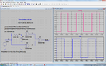
We can shift the phase of sin signal with simple RC opamp circuit. but this circuit can not shift pulse train and makes distortion on output.
which method should we implement in order to phase shift of pulse train?
 

What is the magnitude of required delay ?

+++
 

Frequency of pulse train: 400 Hz
phase shift: 90 degrees
 

Delay = ( 90/360 ) * ( 1/400Hz ) = 625us

Comercial delay-line devices provide maximum time delay in range of 10ns.
Sorry, but I don´t know how to solve the problem with that approach.

+++
 
  • Like
Reactions: nanock

    nanock

    Points: 2
    Helpful Answer Positive Rating
Is it possible for you to use digital gates?

I assumed that the output is also pulses... same frequency but shifted 90 degree
 

It's not really strange job if we want to shift 625uS of 400 Hz pulse train signal, whereas its simply implemented with sinusoidal signal.
actually digital gates work with 0 and 1 levels, however here the amplitude of pulse train is important.
Don't any kind of operational amplifiers shift pulse train signal without any distortion?

below, you can see phase shift of sinusoidal signal, which doesn't work correctly for pulse train.
View attachment phase shift.bmp
 

Sorry I try to figure out what is exactly your signal you like to be processed other than being square wave 400Hz (I mean what is its source?) and what do you expect to get as a result signal after being shifted 90 degree. I guess another square wave with the same amplitude.

Added:
Shifting a square wave 400 Hz (or any other frequency) T/4, could be done by and RC delay circuit and 3 XOR gates (to eliminate transient glitches).
If interested, I will upload the circuit.

Kerim
 
Last edited:

The question that came to me was whether you want an exact 90° shift (i.e., using digital processes) or just an approximate 90° shift using analog procedures. The latter could even be done with even a 555, I believe, or an RC delay into a buffer or inverter(s). The shift would rely on when the threshold was reached.

So, which is it?

John
 

There are 'bucket brigade' IC's available for phase shifting. The principle is of a pipeline.

The ones I know about are made for music. You input an audio signal.

The IC chops it up internally into samples. Then stores each sample as a charge on internal capacitors.

With every clock pulse, the chip shifts every capacitor's charge level to the one next to it.

The output is a re-assembled audio signal, delayed by a certain number of clock cycles, a fraction of a second.

There may be similar IC's that accept pulses rather than audio.

If a cycle is 400 pulses, then it would only need 100 internal capacitors to store 1/4 of a cycle (90 degrees).
 

I conclude from post #6, that the problem should be strictly defined as a 625 µs delay of an analog waveform. This is in fact different from a 90 degree phase shift, which would result in a frequency dependent delay, and not keep the original waveform.

For a constant delay of an analog waveform, a "bucket brigade" IC (analog CCD delay line) as suggested by BradtheRad would be in fact a solution. As far as I know, none of the formerly used devices is still an active part, because they have been replaced by digital delays in all relevant applications. Some are still available at DIY catalog distributors, e.g. Philips TDA1022.
 
  • Like
Reactions: nanock

    nanock

    Points: 2
    Helpful Answer Positive Rating
The pulse period would be 2500 us according to the previous description and the delay 625 us. But besides this point the specification is clear and suggestions have been made.

As an additional question, is the waveform restricted to square waves of varying amplitude? In this case, I can imagine a special circuit that is sampling the input magnitude and generates a delayed square wave of same level. It would be more simple than the suggested analog delay.
 

I am drawing the circuit... using the XOR gates of CMOS series, thus Vcc could range from 3 to 18V.
Hope it will be ok for your application.

Kerim

Added:
Sorry I just noticed your amplitude might vary from 0 to 25V. Therefore the attached circuit won't work for you.
There will be a need for a level tracker at the output block and an up/down level regulator at its input.
 

Attachments

  • PhaseShifter_01.png
    PhaseShifter_01.png
    130.6 KB · Views: 130
Last edited:
Dear Friends

I illustrate the input and output signal below. what we want to know, is the black box circuit.
88_1308480411.png
 
  • Like
Reactions: nanock

    nanock

    Points: 2
    Helpful Answer Positive Rating
The pulse period would be 2500 us according to the previous description and the delay 625 us. But besides this point the specification is clear and suggestions have been made.

Yes, You are right. I had written the frequency mistake. and I corrected it in post #13.

As an additional question, is the waveform restricted to square waves of varying amplitude?

Wave form is a square waves with the frequency of 400 Hz and varying amplitude between 0 ~ 25 Volts. and the desire is shifting the wave 90 degrees without missing amplitude. just this.
 

Sorry I just noticed your amplitude might vary from 0 to 25V. Therefore the attached circuit won't work for you.
As suggested, it can be combined with a S/H circuit sampling the input voltage and an analog switch to generate the variable output pulse.

The other, more general solution is an "analog" delay, either by a CCD "bucket brigade" IC or a ADC/digital delay/DAC chain.
 

That sound likes it's complicated job and it's not as easy as what we do for shifting phase of sinusoidal waveform signal. because shifting sin wave just need op-amp and RC network.

what do you think about this idea:
1st Convert input square wave to sin wave with same amplitude and frequency
2nd Shift its phase by op-amp and RC network which I showed in post #6

is it possible and reasonable to convert square wave to sin wave with same frequency and amplitude?
 

Also a square wave needs only an RC network... the problem is tracking its amplitude at the input from 0V to 25V

Is the square wave signal generated on board or received from another system?
 
Last edited:

Also a square wave needs only an RC network... the problem is tracking its amplitude at the input from 0V to 25V

Is the square wave signal generated on board or received from another system?

1. I simulated shifting phase for square wave with RC network and op-amp first time. this method completely damaged and distort input square signal. I think RC network just works correctly for sinusoidal wave.

2. square signal is generated with something like function generator. its not important that it's inside or outside. what's in your mind?
 

Just curious, since I believe you know very well what you are doing... May I ask you what is the drawback in your opinion about the solution of post #12 ?
 

as you mentioned, the circuit in the post #12 would support input signal with amplitude in the range of 3~18 volts. so if amplitude of input signal would be under 3 volts, the gates will not work correctly and output signal is not proper.
 

Status
Not open for further replies.

Part and Inventory Search

Welcome to EDABoard.com

Sponsor

Back
Top