Continue to Site

Welcome to EDAboard.com

Welcome to our site! EDAboard.com is an international Electronics Discussion Forum focused on EDA software, circuits, schematics, books, theory, papers, asic, pld, 8051, DSP, Network, RF, Analog Design, PCB, Service Manuals... and a whole lot more! To participate you need to register. Registration is free. Click here to register now.

[SOLVED] phase shift in rc circuits

Status
Not open for further replies.

krazyfencer

Junior Member level 2
Joined
Aug 5, 2013
Messages
23
Helped
0
Reputation
0
Reaction score
0
Trophy points
1
Location
East Coast, USA
Activity points
266
Hello,

Hopefully this isn't duplicating any other thread, I've looked but have not found an answer that I understand. I think I understand how a capacitor stores charge in an electric field, and I believe I understand why there is a phase shift in the output of the capacitor with respect to the input. What I am confused about is how and why the capactive reactance and resistance are used to calculate the phase shift.

1) can someone explain the idea behind arctan(theta) = Xc / R? I'm not looking for a mathematical proof, just a simple explanation of how the reactance and resistance defines the shift in phase. Does it have to do with the charging/discharging rate of the capacitor and estimating how 'full' the capacitor is?

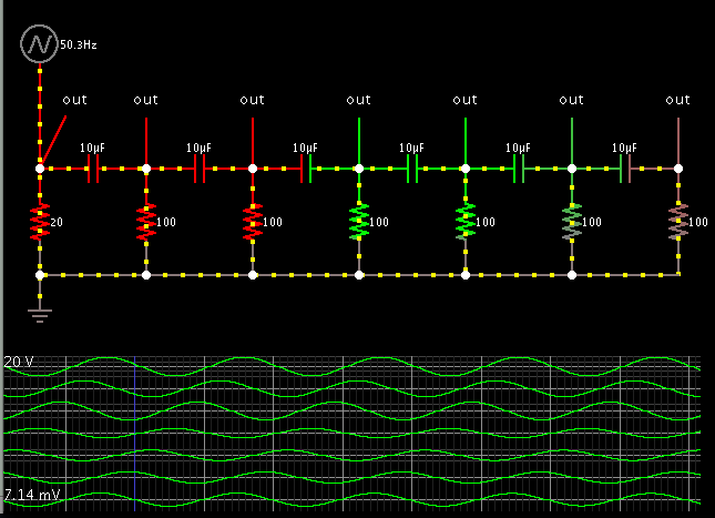
2) which resistance is used for calculating the above formula? The total resistance of the entire circuit? The resistance of just the next resistor in series with the capacitor? So if you have two RC elements like schemeit-project.png, what is the R used to calculate the theta of C1? 1 / (1/R1 + 1/R2) ? Just R1? Does the reactance of C2 contribute to the overall resistance used to calculate the theta of C1?

Thanks!
 

For the general background of reactant AC circuits, you can refer to Lessons in Electric Circuits https://www.ibiblio.org/kuphaldt/electricCircuits/AC/AC_4.html

The arctan(theta) expression can be easily recognized in the phasor diagram describing the complex voltages in the RC circuit.

The simple formula however doesn't apply to the two-stage RC circuit. You can derive a general expression for the circuit's transfer function (output/input voltage), which is a complex function of jω (or "s" in a more general notation). Once you have the transfer function, you can calculate the phase.
 
In addition, a general remark:
If you are asking for the phase shift and/or for the resistance (or any other property of the circuit) you have to specify which NODE you are interested in.
One can probably assume what you mean (for example: phase shift at the node between R2 and C2) - however, for a better understanding it is important for you to realize that these parameters are node dependent.
 

okay, so the link seems to say (unless I've read this wrong), that the phase angle of the output of a series RC circuit is the angle of the vector sum of the reactance and the resistance (which for a single RC element would be the total impedance), right? But it also says that 'When resistors and capacitors are mixed together in circuits, the total impedance will have a phase angle somewhere between 0o and -90o'. So if you have two RC elements (which can apparently have a total phase shift of more than 90 deg), how do you go about constructing this transfer function you are referring to?

@LvW: the phase shifts that I am curious about are the output (versus the input) of each RC element. So for example, what is the phase shift between the input of C1 and the input of C2? Does this shift have any dependency upon the second RC element (C2 and R2)? And if so (which I'm pretty sure it does), how does one actually calculate the shift?
 

To help us grasp the dynamics of these types of interactions, this is where an animated simulator shines.

Here is a simulation of 6 stages of your original schematic, consisting of capacitors in series, with resistors to ground. (Created in Falstad's simulator.)


I added a resistor at the left, to indicate the phase of the signal coming from the waveform generator.

The first capacitor advances the incoming waveform by a certain amount of degrees.

You can increase the phase shift by (a) increasing Farad value, (b) increasing resistor value, or (c) reducing frequency.

The second capacitor takes the output from the first, and advances it further. The second capacitor is not influenced by the original applied signal.

Each stage attenuates the signal.

By adding sufficient stages, the waveform can be advanced more than 360 degrees.

By clicking the link below, it will open the website falstad.com/circuit, load by schematic, and run it on your computer. You can watch the animated action on your screen. The movement of current bundles indicates how each stage reacts to the preceding stage.


You can change values by right-clicking a component, and select Edit.

Likewise you can change the frequency.
 
The formula you give for theta applies only to a simple RC voltage divider. In general, the phase shift is equal to the arctan of Imag(T)/Real(T), where Imag(T) is the imaginary component of the transfer function, and Real(T) is the real component of the transfer function. The transfer function is the output voltage divided by the input voltage. The output voltage can be determined by standard linear circuit analysis techniques.
 
Sorry for the delay, but thanks for the help. So it looks like the bottom line is that it is more complicated than I thought and the equation I was told only applies to a single RC element.
 

Status
Not open for further replies.

Part and Inventory Search

Welcome to EDABoard.com

Sponsor

Back
Top