Continue to Site

Welcome to EDAboard.com

Welcome to our site! EDAboard.com is an international Electronics Discussion Forum focused on EDA software, circuits, schematics, books, theory, papers, asic, pld, 8051, DSP, Network, RF, Analog Design, PCB, Service Manuals... and a whole lot more! To participate you need to register. Registration is free. Click here to register now.

[SOLVED] Phase noise measurement using spectrum analyzer

Status
Not open for further replies.

palmeiras

Full Member level 6
Joined
Feb 22, 2010
Messages
375
Helped
61
Reputation
122
Reaction score
50
Trophy points
1,308
Location
South America
Activity points
4,199
Hi guys,

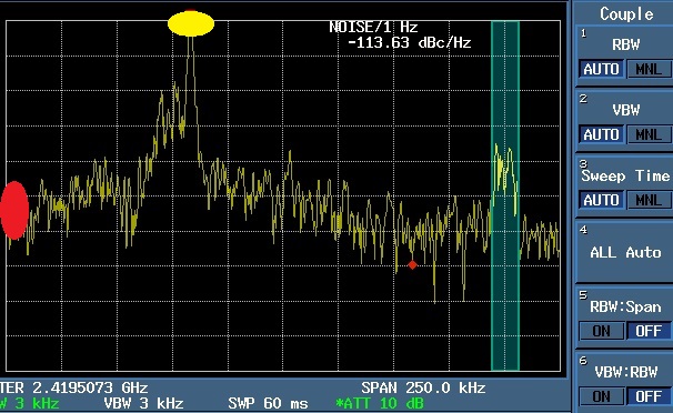
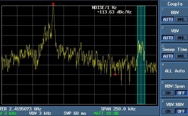
We have measured the phase noise using a spectrum anayzer and the result are shown in the attached figure.


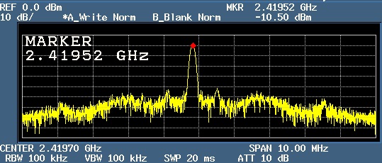
However, I don't know why the spectrum is not "clean line" as given in the attached example, presented on the manual of the spectrum analyzer.


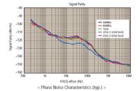
Please, do you have an idea of what it is happening? How can I get a "clean" line"? I guess it is something related to the spectrum analyzer configuration.

The oscillator has a traditional LC-tank architecture.
Thank you very much. Best Regards,
 

Enable the video filtering, that is lower the number under VBW. Usually I have the ratio VBW:RBW=0.1 or even 0.01. Keep the sweep time to auto to have a calibrated measurement.
 
  • Like
Reactions: palmeiras

    V

    Points: 2
    Helpful Answer Positive Rating

    palmeiras

    Points: 2
    Helpful Answer Positive Rating
Hi rfmw!
Thank you very much for your reply.
The sweep time, RBW and VBW are auto in this measurement. It seems that VBW and RBW is 3 kHz.
Only the options: RBW:Span and VBW:RBW are off.
Are you saying to tyrn on VBW:RBW and set it like 0.01. What does it mean?
As the measuremnt given is SSB, I dont understand why there is also spectrum in the left side of the peak. The oscillation frequency is 2.41 GHz.
Do you understand that?
Do you have another ideia about what is happening?
 

Yes, your current VBW is 3kHz. Set it to 100Hz or so. For example, with a VBW:RBW=0.01 your RBW will stay at 3kHz, but VBW will lower to 30Hz. Your trace will become cleaner without the noise. Your spectrum appears to be very noisy or is even modulated. You should measure the PN on CW signal only (and make the VCO power supply as clean as possible - battery powered if possible).
 
rfwm,
Thanks again. I'm going to reduce the video bandwidth. I'm interested on measuring the phase noise until 250 kHz.
What value should be set the RBW:span?

please, what do you mean with "measure the phase noise on CW signal"? could you explain?

Based on the attached figure, where do you think that is the 1 Hz off-set frequency? Yellow or red point?


Select the span of about 300kHz or 400kHz and position the signal peak to let say 1st division from the left of the screen.

CW means unmodulated carrier-wave signal, like the one from an oscillator (no wanted or unwanted modulation applied to the VCO). But from your picture it is not clear what the signal is, where's the peak, the sidebands are unequal. I'd say you have a very noisy or unstable signal. Most probably you wont be able to measure any realistic phase-noise value from this signal. Make a photo with larger span (i.e. 2Mhz, or even more various spans) and remove the coloured dots from the picture for us to see what you're dealing with.
 
Hi rfmw,

Thank you so much. we are going to test this recommendation and come back. Bellow, there is the spectrum without using the phase noise capability.

I guess it is not possible to figure out the issue through this figure. But, anyways,

do you see something strange?


- - - Updated - - -
 

This measurement is much better. I suppose you have a free-running VCO (not phase-locked)? Be sure to clean the power supply and Vtune as much as possible (1000uF in parallel to 1nF and 100nF on both inputs). Using a battery for the power supply would be the best option. Then slowly reduce the span and see how "wild" or noisy is your carrier. Then decide at what span value it would be the best option for you to measure your PN value. If you'll have too narrow span, your PN measurement will be useless. Try and experiment.
 
hi rfmw,
Actually we did this two measurements together:
(i) the first one was using the phase noise function in the spectrum analyzer and we got that strange results, measured in dBc/Hz.
(ii) the second measurement was only the spectrum, measured in dBm/Hz.
How do you calculate the phase noise based on this dBm/Hz data? Only divided all values by the carrier power, and is it all?
Another "issue" is that the frequency step of this measurement was 10kHz. It is not enough precision. I'm trying to find how we can decrease the frequency step, for instance, to 100Hz.
please what do you mean with "if you'll have too narrow span, your pn measurement will be useless"?. I wish to measure the phase noise at 1 kHz, 10 kHz, 100 kHz.
Obs: we dont have Vtune in my oscillator. I decided to remove this node in order to make easier the measurements and eliminate the needed of PLL to measure it.
Thank you very much,
 

Status
Not open for further replies.

Part and Inventory Search

Welcome to EDABoard.com

Sponsor

Back
Top